
CB85-10 leakage protection circuit

The CB85-10 leakage protection circuit is designed to enhance safety by detecting leakage currents and disconnecting the electrical supply to prevent electric shocks. The circuit includes a trip coil (T), which is the actuator responsible for opening the circuit when a leakage is detected. The test button (SB) allows users to simulate a fault condition to verify the functionality of the protection circuit. The simulated human resistance (Ri) represents the resistance of a human body, which is critical for determining the threshold at which the circuit will activate.
In this schematic, the trip coil is connected to a relay that interrupts the power supply when a leakage current exceeds a predetermined level. The test button is strategically placed in the circuit to facilitate routine testing, ensuring that the leakage protection system is operational. The simulated human resistance is typically set to approximate the resistance of a person under fault conditions, allowing the circuit to react appropriately to real-world scenarios.
The circuit operates under the principle of differential current sensing, where the current flowing through the live and neutral wires is continuously monitored. If a difference in current is detected, indicative of leakage, the trip coil is energized, causing the relay to open and disconnect the load. This design emphasizes reliability and safety, making it suitable for various applications in residential and commercial electrical systems. Regular testing via the test button is essential to maintain the integrity of the leakage protection mechanism. CB85-10 leakage protection circuit diagram, T for the trip coil, SB is the test button, Ri is simulated human resistance
Related Circuits

A flip of 51 activates the system. Power for the circuit is derived from the ignition switch, and the circuit receives no power until the ignition switch is closed. When the camera is powered on, capacitor C1 is charged,...

The circuit reduces the effective peak current of the output PUT, Q2. It allows the capacitor to charge with a high gate voltage and periodically lowers the gate voltage. When Q1 fires, the timing resistor can be set to...
ETl3X220 is a cost-effective single-chip transmitter that operates via RF communication. It supports up to 10 channels and is ideal for applications such as wireless mice, keyboards, and other communication devices. The main technical features include: - Analog FM...

The relays in the AC arc welding machine manage the load through a three-way power circuit, as depicted in Figure 522. The selected relay type is KA, operating at 24V. Additionally, the time relay KT is of the JS7...
For the simplest functions, such as a flashing indicator and/or beeper, a printed circuit board is not necessary. Components can be directly soldered onto the legs of the PIC microcontroller, using heat-shrinkable sleeves for insulation. Caution is advised to...
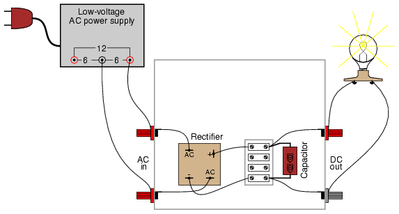
A bridge rectifier module is strongly recommended over building a bridge rectifier circuit using individual diodes. These modules are designed to be mounted on a metal heat sink. A metal enclosure is preferred over a plastic one due to...