
Hysteresis-free phase control circuit

The described circuit utilizes a single RC phase lag network to achieve effective dimming control for lamps. The primary components of this circuit include a resistor (R) and a capacitor (C), which together create a time delay that allows for the modulation of the voltage applied to the lamp. The phase lag introduced by the RC network is crucial in determining the timing of the gate signal, which controls the power delivered to the load.
In operation, the circuit begins with the capacitor charging through the resistor during each positive half cycle of the AC waveform. The voltage across the capacitor gradually increases, and once it reaches a predetermined threshold, it triggers the gate of a semiconductor device, such as a triac or a thyristor. This action allows current to flow to the lamp, thus illuminating it. The degree of dimming is controlled by adjusting the values of the resistor and capacitor, which affects the charging time of the capacitor.
To mitigate the hysteresis effect, which can cause the lamp to flicker or snap on abruptly, the circuit incorporates a mechanism to reset the capacitor to approximately 0 volts at the end of each positive half cycle. This is achieved through the gate lead, which discharges the capacitor quickly, ensuring that it does not retain a significant charge when the next half cycle begins. This reset action maintains smooth operation and prevents erratic behavior of the lamp.
Overall, the described circuit is an efficient solution for lamp dimming applications, leveraging simple components to achieve reliable performance while minimizing undesirable effects such as flickering. Proper selection of the resistor and capacitor values, as well as careful design of the reset mechanism, are essential for optimal functionality.This circuit is intended for lamp dimming and similar applications. It requires only one RC phase lag network To avoid the hysteresis (or "snap-on") effect, the capacitor is reset to approximately 0 volts at the end ofevery positive half cycle using the gate lead. 🔗 External reference
Related Circuits
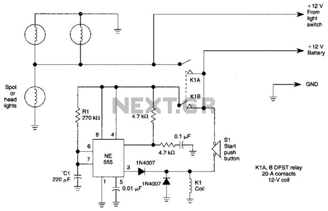
Pressing the START pushbutton activates either the headlights or spotlights for a specified duration. After 1 minute, determined by R1 and C1, the lights will turn off as the NE555 timer completes its cycle. The circuit utilizes a NE555 timer...
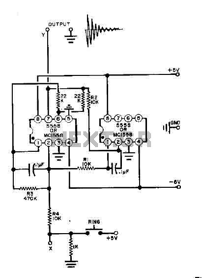
This simple bell circuit utilizes two 555 timers. The frequency is regulated by capacitors that should maintain nearly identical values for optimal performance. Fine-tuning is achieved using resistors R1 and R2. Additionally, the decay time is managed by resistor...
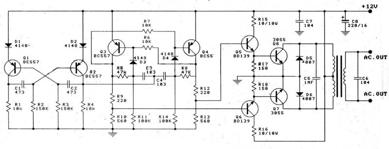
A 12V car battery is recommended as the input for this circuit, utilizing the 2N3055 transistor as the amplifier. This configuration can deliver a power output of up to 100W, making it suitable for use in battery chargers, emergency...
This integrated circuit is highly efficient and does not require any external glue logic for operation. It features two pins for motor control: one pin is dedicated to controlling the direction of the motor, while the other pin is...
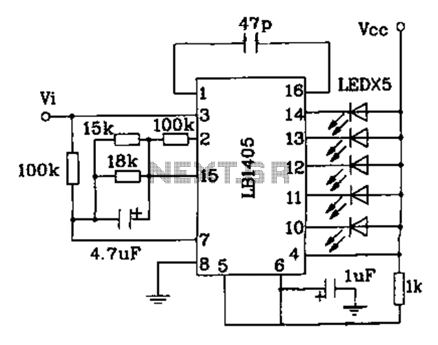
The LB140 is depicted in Figure as a typical driver IC circuit for a five-digit LED level indicator. The BL1405 is commonly utilized in tape recorders for level indication. The LB140 integrated circuit serves as a driver for five-digit LED...

This circuit is designed for an LM1893 power line modem, which facilitates information transfer between remote locations using the power mains. The LM1893 serves as a power line interface for half-duplex (bi-directional) communication of serial bit streams employing various...