
LED indication Integrated Circuits

The LB140 integrated circuit serves as a driver for five-digit LED displays, facilitating visual representation of audio signal levels. This functionality is critical in audio equipment such as tape recorders, where accurate level indication is essential for optimal performance and sound quality. The circuit typically comprises several key components, including the LB140 IC, a series of resistors, capacitors, and the LED display itself.
The LB140 operates by receiving an audio signal input and processing it to drive the LEDs, which light up in response to the amplitude of the input signal. The circuit is designed to convert the analog audio levels into a digital format that can be visually represented, ensuring that users can easily monitor the signal levels during recording or playback.
In a typical application, the audio input is fed into the LB140, which amplifies and rectifies the signal. The resulting voltage level is then compared against predetermined thresholds, with each threshold corresponding to a specific LED in the display. As the audio level varies, different combinations of LEDs illuminate, providing a clear and immediate visual indication of the signal strength.
Additionally, the BL1405, as a variant, may include features such as built-in calibration options or enhanced sensitivity, making it suitable for a wider range of audio equipment. This versatility allows for its integration into various designs, ensuring that it meets the needs of both consumer and professional audio applications.
The overall design of the circuit emphasizes reliability and ease of use, making it an essential component in modern audio recording and playback devices.LB140 is shown in Figure Five-digit LED level indicator typical driver IC circuit, BL1405 widely used tape recorders and tape recorders do with level indication.
Related Circuits
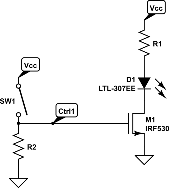
A 4-position slide switch is utilized to activate different colored LEDs based on its position. Additionally, it is required to adjust the output frequency of a 555 timer operating in astable mode to drive a piezo buzzer. The challenge...
This circuit is based around HT2050 manufactured by HOLTEK semiconductors. It is a low cost, low-power C-MOS LSI designed for lamp and LED flash driver. It requires minimum external components. You can operate it with just two AAA cells...
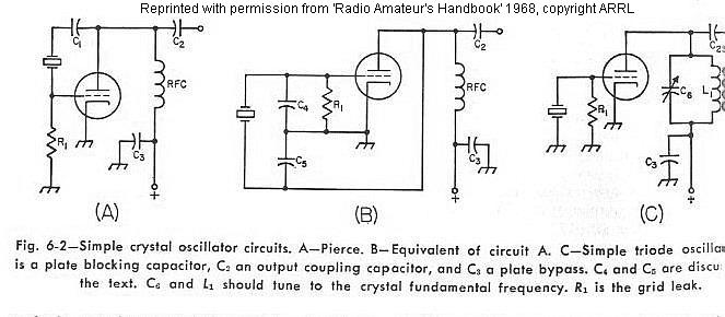
The frequency of a crystal-controlled oscillator is maintained with high precision through the use of a quartz crystal. The frequency is primarily determined by the dimensions of the crystal, particularly its thickness, while other circuit parameters have minimal impact....
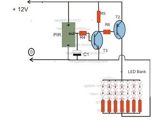
The circuit is an LED driver that responds to ambient light as well as the presence of an intruder, varying its illumination accordingly. Additionally, it includes an ambient light sensor to turn the LEDs on and off, and a...

A simple linear voltage-controlled amplifier can be constructed with one operational amplifier (op amp) and two junction field-effect transistors (JFETs). This amplifier can achieve an 80-dB dynamic control range with less than ±0.2% linearity error for 0 V. The described...
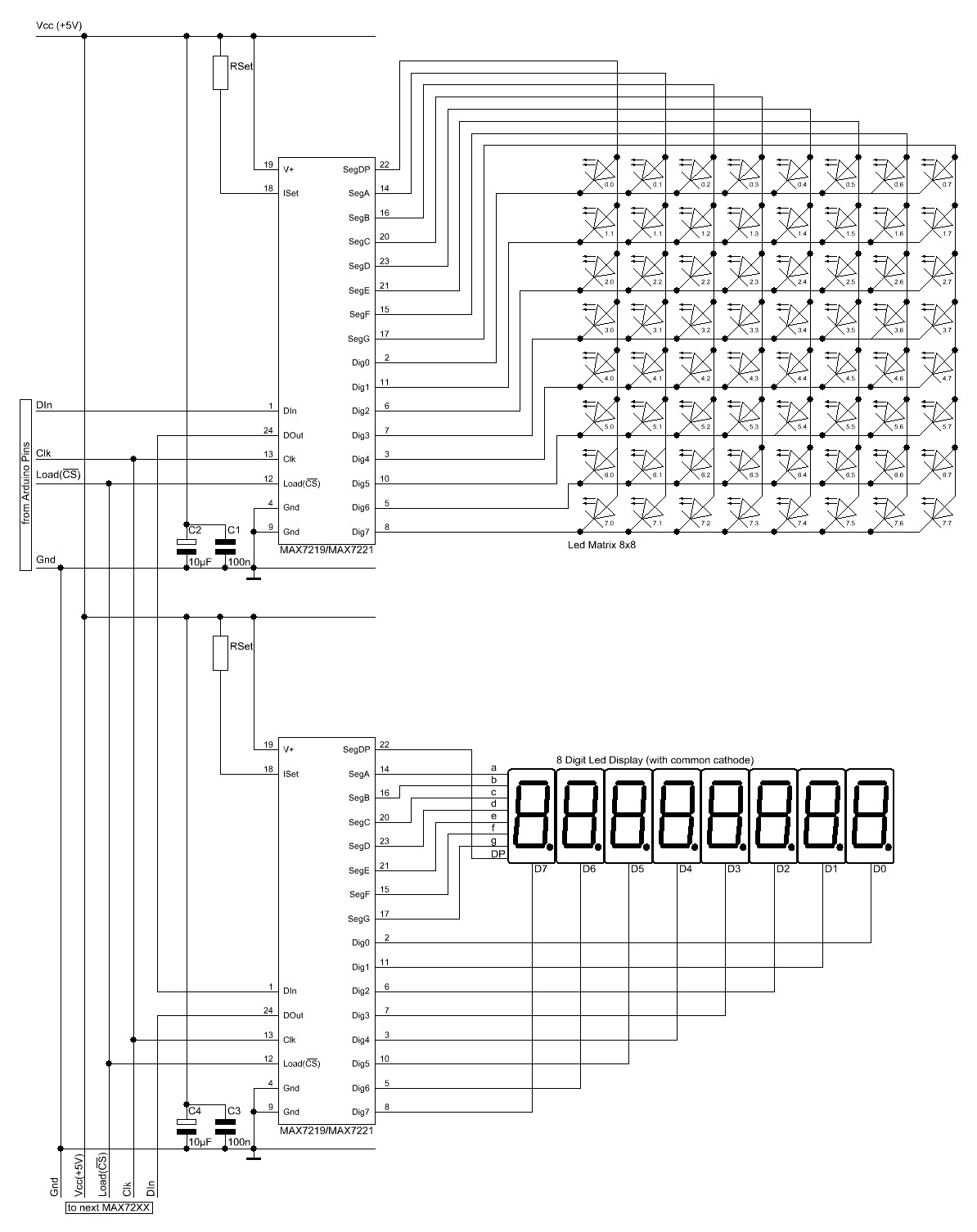
The Arduino website provides comprehensive documentation on connecting LEDs to the Arduino using the MAX7221. A specific set of components is required for this setup. The MAX7221 is a versatile LED driver that enables the control of multiple LEDs through...