
I ran a code on my 99 dodge ram 1500 and it came back with

The circuit testing procedure described involves the use of an analog voltmeter to assess the functionality of the camshaft position sensor within an automotive system. This test is critical for ensuring accurate engine timing and synchronization, which are essential for optimal engine performance.
The analog voltmeter provides real-time voltage readings that reflect the operation of the camshaft position sensor as the engine is cranked. The use of paper clips to access the distributor connector terminals allows for a non-invasive method of measuring voltage without disconnecting the harness, thereby preserving the integrity of the connections.
During the test, a voltage reading below 1 volt indicates that the sensor is not triggering, while a peak reading of 5.0 volts confirms that the sensor is active and responding to the high and low points of the wheel. If the expected voltage levels are not observed, further diagnostics are necessary. Checking the voltage at cavity A-17 of the 32-way connector serves as a troubleshooting step to ensure that power is reaching the sensor from the engine controller.
Continuity tests between the distributor connector and the specified cavities in the engine controller are essential to identify any breaks or faults in the wiring that could impede the sensor's operation. The requirement for a DRBII scan tool or equivalent for further diagnostics emphasizes the complexity of modern automotive electronics, where precise communication between components is vital for system functionality.
In conclusion, this test not only verifies the operational status of the camshaft position sensor but also highlights the importance of maintaining proper electrical connections within the vehicle's wiring harness. Ensuring continuity and voltage levels are within specified ranges is crucial for diagnosing potential issues that could affect engine performance and reliability.For this test you will need an analog (non-digital) voltmeter. Do NOT remove the distributor connector. Using small paper clips, insert them into the backside of the distributor wire harness connector to make contact with the terminals. Do NOT damage the connector when inserting the paper clips. Attach the voltmeter leads to these clips. Turn the ignition ON. Rotate the engine. The meter should show a reading of less than 1 volt and a high voltage reading of 5. 0 volts as the high and low points on the wheel pass the sensor. If 5. 0 volts is not found at the supply wire, check for voltage at cavity A-17 of the 32-way connector. Leave the engine controller harness connected for this test. NOTE If voltage is not found at the PCM connector, you will need to diagnose the system using a DRBII scan tool, or equivalent, or take the vehicle to a qualified shop. Check continuity between the sensor and supply wire. This is checked between the distributor connector and cavity A-17. If continuity is not present, repair the wire harness. Check for continuity between the camshaft position sensor output wire and cavity A-18 at the engine controller.
If continuity is not present, repair the wire harness. Crank the engine while observing the voltmeter. The voltmeter needle should fluctuate 0-5 volts, approximately. This will verify the camshaft position sensor is operating properly and a sync pulse signal is being generated. 🔗 External reference
Related Circuits
This power factor controller accepts voltages ranging from 90 to 268 Vac, which is why it is referred to as a power factor controller with universal input, as it accommodates the mains supply standards in nearly any country. The...
This website was developed to assist students in discovering ideas for their projects or final year projects (FYP). All content presented here is sourced from reliable blogs, websites, and forums. The owner of this website assumes no responsibility for...
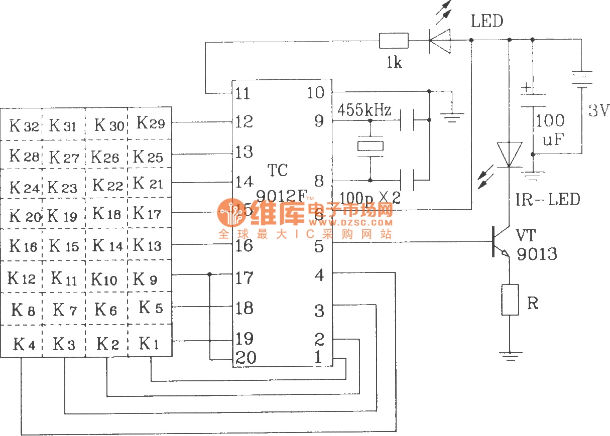
The TC9012 is a specialized off-screen remote control code transmitter. It incorporates an oscillator, divider timing generator, system code latch, data storage, key scan input, key scan output, and carrier control and output units. The internal 8-bit system code...
CrustCrawler develops and manufactures advanced walking robots and robotic accessories. CrustCrawler specializes in the design and production of innovative walking robots, which incorporate advanced technologies and engineering principles to achieve improved mobility and functionality. These robots are typically characterized by...
The Boss SD-1 Super OverDrive is a pedal characterized by a straightforward design, incorporating a dual operational amplifier (uPC4558C) and six transistors, along with an asymmetric overdrive circuitry that emulates the classic, natural growl of a tube amplifier. It...
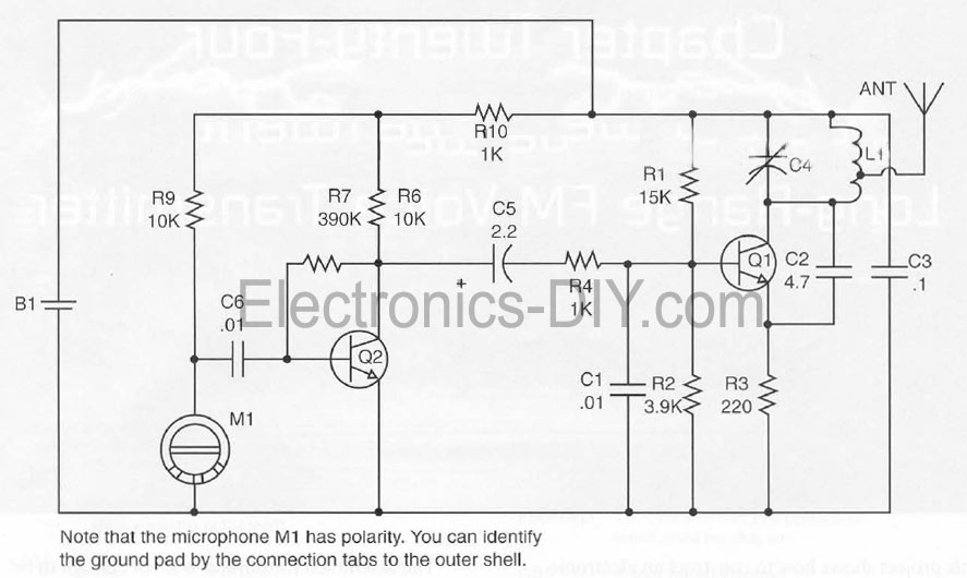
This document presents a Long Range FM Transmitter circuit, which is a highly sensitive, low-power FM transmitter. It includes a radio frequency (RF) oscillator section connected to a high-sensitivity, wide pass-band audio amplifier and a capacitance microphone equipped with...