
Optical communication system
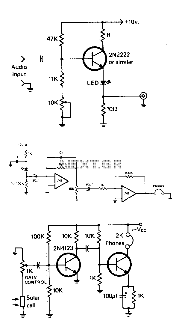
The described circuit features a basic modulator stage designed to work with standard light-emitting diodes (LEDs). The primary function of this circuit is to modulate the LED's brightness in response to an audio signal. The core component is a transistor, which acts as a variable resistor controlled by a potentiometer. By adjusting the potentiometer, the biasing of the transistor is altered, allowing the LED to reach a predetermined half-output level. This midpoint serves as a reference for modulation, enabling the LED to fluctuate in brightness above and below this set point in accordance with the incoming audio signal.
To ensure safe operation, resistor R1 is employed to limit the current flowing through the LED. This is crucial, as excessive current can damage the LED and reduce its lifespan. The value of R1 is selected based on the LED's forward voltage and current specifications, ensuring that the LED operates within its rated limits.
Additionally, a 10-ohm resistor is placed in the circuit to facilitate the observation of the modulating signal on an oscilloscope. This resistor allows a small portion of the audio signal to be tapped off, providing a means to visualize the modulation characteristics. By connecting an oscilloscope across this resistor, one can monitor the waveform of the audio signal and assess how effectively it modulates the LED's brightness.
Overall, this simple modulator stage circuit effectively combines audio modulation with LED control, making it suitable for various applications where visual feedback is required in response to audio signals.The simple modulator stage will accommodate most common LEDs. By adjusting the potentiometer, the bias of the transistor is varied until the LED is at its half output point. Then, audio will cause it to vary above and below this point The purpose of Rl is to limit the current through the LED to a safe level and the purpose of the 10 ohm resistor is to allow a portion of the modulating signal to be observed on a scope. 🔗 External reference
Related Circuits
The water resource is being transformed into a valuable and rare commodity. Consequently, promoting water-saving irrigation has become a priority for countries worldwide to address the water resource crisis and achieve agricultural modernization. This text proposes a cipher scheme...
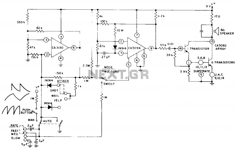
The circuit utilizes a CA3130 BiMOS operational amplifier configured as a multivibrator to regulate the siren's frequency. A CA3094 is employed as a voltage-controlled oscillator (VCO), which is subsequently connected to a CA3082 transistor array that drives a speaker....
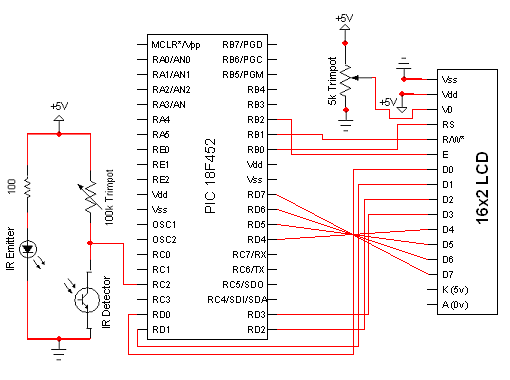
The circuit for the Digital Tachometer/RPM Counter consists of only a few devices. Wire them up according to the following circuit diagram. The PIC used is on a demonstration board, which means the clock, power, and ground pins are...
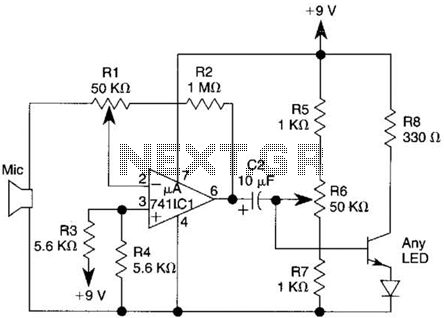
This transmitter utilizes a 741 operational amplifier as a high-gain audio amplifier, which is activated by a microphone. The output of the 741 is connected to Q1, functioning as the driver for an LED. Potentiometer R1 serves as the...
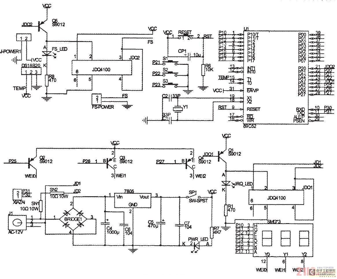
The primary principle of the system is to gather real-time temperature data from a temperature sensor using a microcontroller, which then compares this data with pre-defined thermostat values to maintain the desired temperature within a sample container. This text...
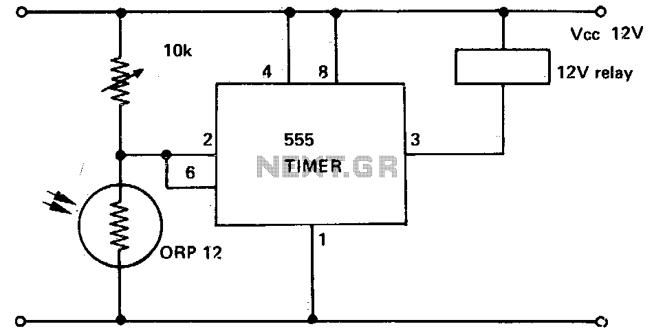
This circuit illustrates a 555 timer with its trigger and threshold inputs connected together, which is utilized to activate a relay when the light level detected by a photoconductive cell drops below a predetermined threshold. Additionally, this circuit can...