
I2C using (MSSP)
The I2C (Inter-Integrated Circuit) protocol is a widely used communication interface for connecting microcontrollers to various external peripherals, such as port expanders, EEPROMs, and real-time clocks. In this application, the Master Synchronous Serial Port (MSSP) module of the PIC18 microcontroller is configured to operate in I2C mode to communicate with the MCP23017 port expander from Microchip Technology.
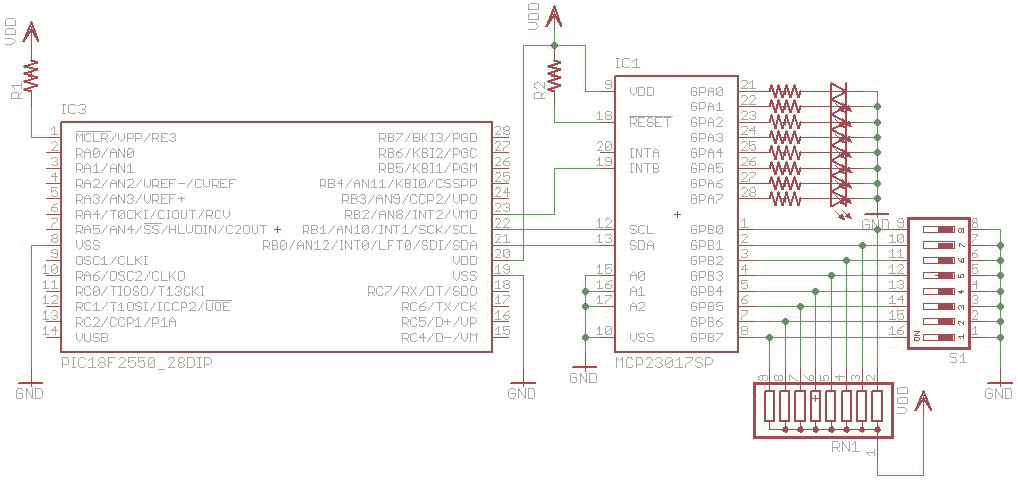
The circuit is implemented on a breadboard, allowing for easy testing and modification of the MSSP functionality as an I2C master. The DIL switch connected to Port B of the PIC18 is utilized to control the LEDs connected to Port A of the MCP23017. This setup enables the user to manipulate the state of the LEDs based on the input from the DIL switch.
The INTB pin of the MCP23017 is connected to the INT2 pin of the PIC18, facilitating an interrupt-driven approach to update the PORTA output of the MCP23017 based on the DIL switch's state. Two interrupts are employed in the code: a high-priority interrupt for handling external interrupts and a low-priority interrupt for managing the MSSP module's operations.
To initialize the MSSP module in I2C master mode, specific configuration settings must be applied. This includes setting the appropriate clock frequency and enabling the I2C functionality. The code snippet for initializing the MSSP module is crucial for ensuring proper communication with the MCP23017.
Functions for data transmission and reception, namely `i2cTransmit` and `i2cReceive`, are created according to the I2C protocol specifications outlined in the MCP23017 datasheet. These functions manage the loading of data buffers for sending and receiving data over the I2C bus. The interrupt service routine handles the transmission and reception processes, ensuring that data is passed to and from the MSSP module as per the defined protocol.
Overall, this circuit design exemplifies the integration of I2C communication with the PIC18 microcontroller, showcasing the use of interrupts and the MSSP module to effectively interface with the MCP23017 port expander for controlling multiple outputs based on user input.I2C are widely use for to communicate with external peripheral such as port expender, EEPROM, Real Time Clock etc. The Master Synchronous Serial Port (MSSP) module in PIC18 can be used to communicated with I2C peripheral.
MSSP module can be configure to work as SPI and I2C. In this example the module will be configured as I2C to communicate with a port expender from Microchip MCP23017. The circuit below is built up on breadboard to test the MSSP function as an I2C module. The DIL switch on Port B is used to control the LED on Port A of the IO expender. INTB from the IC is connected to the INT2 pin of the PIC so that the PORTA output of the Port expender can be updated with the value from the DIL switch. The code function will be implemented using 2 interrupt, one at the high priority location for the External interrupt and the other for MSSP module at the low interrupt.
MSSP module had to be configured as I2C master mode for this example. The code below shows the setting to initialize MSSP module. unction for sending and receiving data for I2C is created according to the required protocol to communicate with MCP23017. The code below shows the function i2cTransmit and i2cRecieve for receiving data and the interrupt routine for the handling of transmission/reception.
The 2 function is used to load the data buffer for transmission and reception. The Interrupt function will pass the data accordingly to the MSSP module according to the protocol written in the datasheet of MCP23017. 🔗 External reference
Related Circuits
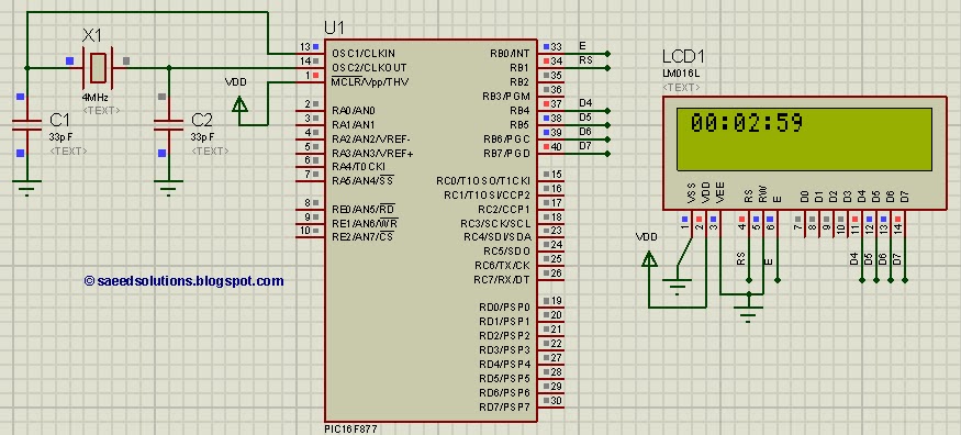
This tutorial on the PIC16F877 microcontroller addresses the question, "How to implement a digital clock using the PIC16F877?" The use of the PIC16 simulator (Proteus) is included. The PIC16F877 microcontroller is a versatile and widely used component in embedded systems,...
A radio remote control system utilizing DTMF (Dual-Tone Multi-Frequency) technology is presented. This circuit allows for the control of various electrical appliances through radio frequency signals. The described radio remote control system employs DTMF tones, which are generated by a...

A compact audio amplifier circuit utilizing the TDA 7052 integrated circuit from Philips. This circuit is suitable for use as a pocket radio amplifier, delivering an output power of 2 watts. The TDA 7052 is a low-voltage audio amplifier designed...
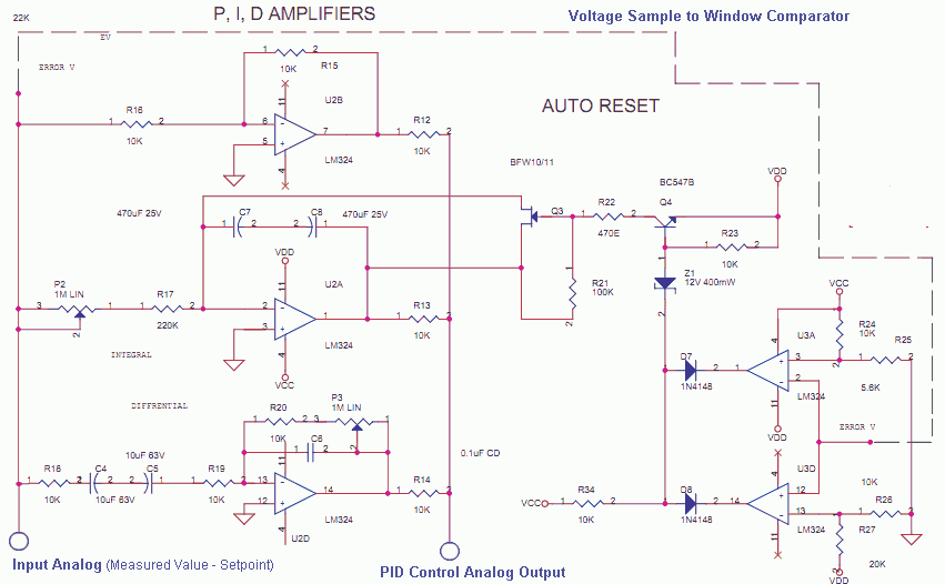
The Measured Value and the Setpoint are two inputs to a control system. The Measured Value is the amplified input from a transducer or sensor for a specific parameter that requires regulation, such as pressure or temperature. The Setpoint...
The IR3721 is a versatile power or current monitoring integrated circuit (IC) designed for low-voltage DC-DC converters. It monitors the inductor current in buck or multiphase converters by utilizing either a current sensing resistor or the inductor's winding resistance...

This is the design circuit diagram of an ultrasonic mosquito repeller. The circuit operates based on the theory that insects, such as mosquitoes, can be repelled by sound frequencies in the ultrasonic range (above 20 kHz). The circuit utilizes...
Warning: include(partials/cookie-banner.php): Failed to open stream: Permission denied in /var/www/html/nextgr/view-circuit.php on line 713
Warning: include(): Failed opening 'partials/cookie-banner.php' for inclusion (include_path='.:/usr/share/php') in /var/www/html/nextgr/view-circuit.php on line 713