
IC 2 tones Siren
This circuit is designed to produce two distinct sound effects commonly associated with emergency vehicles: a double-tone siren reminiscent of police or fire brigade vehicles, and a single-tone siren akin to older ambulance sounds. The circuit can be powered by batteries, making it suitable for use in a variety of applications including bicycles, battery-operated cars, motorcycles, and toy models.
The core of the circuit utilizes integrated circuits (ICs) configured as oscillators. When the switch SW1 is in the position designated for the double-tone sound, the oscillation is generated by the gates IC1A and IC1B. These gates are typically configured in a way that allows them to produce two different frequencies simultaneously, resulting in the characteristic dual-tone sound.
Switching SW1 to the alternate position activates a different section of the circuit involving IC1C and IC1D. In this configuration, pressing the pushbutton P1 initiates an oscillation that increases in frequency and subsequently decreases, mimicking the sound of an old ambulance siren. This functionality adds an interactive element to the circuit, allowing users to control the sound output dynamically.
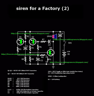
The output of the circuit is routed to a loudspeaker, which is driven by transistor Q1. The choice of loudspeaker is critical; it should be of adequate size and housed properly to ensure that the sound is both loud and realistic. The performance of the sound can be further fine-tuned by adjusting the values of capacitors C1, C2, C5, and C6, as well as any associated resistors. These components influence the tone and duration of the sound oscillations, allowing for customization based on user preference.
Overall, this circuit serves as an engaging and entertaining addition to various children's toys and vehicles, providing realistic sound effects that enhance the play experience.Double-tone Police sound Single-tone old ambulance sound This circuit is intended for children fun, and can be installed on bicycles, battery powered cars and motorcycles, but also on models and various games and toys. With SW1 positioned as shown in the circuit diagram, the typical dual-tone sound of Police or Fire-brigade cars is generated, by the oscillation of IC1A and IC1B gates.
With SW1 set to the other position, the old siren sound increasing in frequency and then slowly decreasing is reproduced, by pushing on P1 that starts oscillation in IC1C and IC1D. The loudspeaker, driven by Q1, should be of reasonable dimensions and well encased, in order to obtain a more realistic and louder output. Tone and period of the sound oscillations can be varied by changing the values of C1, C2, C5, C6 and/or associated r
🔗 External reference
Related Circuits

The circuit outlined here is capable of producing three distinct US-style siren sounds: police, ambulance, and fire engine. The sound selection is facilitated by switch S1. This circuit is applicable in various contexts, including toys (such as model vehicles),...

This circuit is intended for children fun, and can be installed on bicycles, battery powered cars and motorcycles, but also on models and various games and toys. With SW1 positioned as shown in the circuit diagram, the typical dual-tone...
This is a powerful siren circuit diagram. This circuit can provide significant support for alarm systems, enabling users to achieve optimal results. The siren circuit is designed to produce a loud sound for alerting purposes, commonly used in security systems,...
This circuit generates a double tone sound similar to that of a police siren and a single tone sound reminiscent of an old ambulance. It is typically installed in battery-powered vehicles such as cars and motorcycles. The circuit utilizes a...
This alarm siren circuit produces a warbling sound, suitable for use in toys or security alarms. The circuit employs two 555 IC oscillators. The first oscillator generates the audio frequency, while the second oscillator creates a modulating signal. This...
The core of the circuit is a two-transistor flasher, with frequency modulation applied to the base of the first transistor. When the pushbutton is pressed, the oscillation frequency increases to a peak, and upon releasing the button, the frequency...