
Wailing Alarm Siren
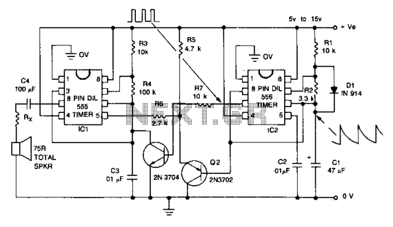
The alarm siren circuit is designed to generate a characteristic warbling sound by utilizing two 555 timer ICs configured as oscillators. The first 555 timer is set up in astable mode, producing a continuous square wave output that defines the base audio frequency of the alarm. The second 555 timer functions as a modulator, altering the frequency of the first oscillator's output to create the desired warbling effect.
The circuit's performance can be fine-tuned by adjusting the capacitance of capacitor C1. The range of 10 µF to 47 µF allows for experimentation to achieve different warbling frequencies, which can be particularly useful in customizing the sound for various applications, whether in toys or security systems. The duration of the warbling sound is determined by the timing components connected to the first 555 timer, which can be calculated using standard 555 timer equations.
Power supply considerations are crucial for the reliable operation of the circuit. The recommended voltage range is between 5V and 15V, with caution advised at higher voltages. The 555 timer is known to generate heat, especially when operated at 12V or above, which can lead to thermal stress and reduced longevity of the component. Therefore, heat dissipation measures or voltage regulation might be necessary for prolonged use.
The circuit also includes a correction note indicating that transistor Q1 should be a 2N3906 instead of the 2N3904, ensuring proper functionality based on the testing conducted. This detail is important for anyone replicating the circuit to avoid performance issues.
Overall, this alarm siren circuit is a versatile and effective solution for generating an auditory alert, with several adjustable parameters to tailor its performance to specific needs.This alarm siren circuit produce warbling sound, you can use it in your toys or in security alarm. The circuit use two 555 IC oscillator. In this alarm siren circuit, the first oscillator is employed to produce audio frequency. The second oscillator is employed to produce a modulating signal. This modulating signal make this alarm siren generates warbling sound. You can try to change the capacitor C1 to change the warbling frequency. Using the component shown in the schematic diagram, this alarm siren gives 6 seconds warbling period. You can lower the C1 capacitor value to get higher warbling frequency, for example, you can try some values between 10 uF to 47 uF to get the suitable effect.
This alarm siren circuit works with 5-15V power supply, but note that the 555 IC would suffer a significant self-heating when you use 12 volts or higher, and this may cause a shorter lifetime for the 555 IC chip. ERRATA: Q1 should be 2N3906, NOT 2N3904 (thanks to Nils Nelson for building and testing this circuit).
Be the first of your friends to get free diy electronics projects, circuits diagrams, hacks, mods, gadgets & gizmo automatically each time we publish. Your email address & privacy are safe with us ! 🔗 External reference
Related Circuits
The original smoke alarm circuit has several issues that have disappointed hobbyists and students. Instead of attempting to fix these problems, an update has been created using the well-known LM741 operational amplifier. This new design is simpler, more conventional,...
The signal begins at a low frequency, increases over a duration of approximately 1.15 seconds to a high frequency, pauses for about 0.35 seconds, and then resumes its ascent from a low frequency, continuing this pattern indefinitely. The described signal...
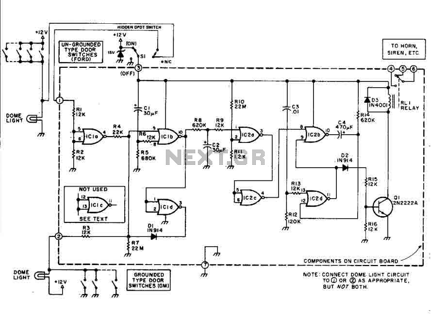
This car alarm circuit features an 18-second delay for both entrance and exit. It sounds continuously for 6 minutes before automatically turning off the horn and preparing for the next triggering event. The alarm remains activated even if the...
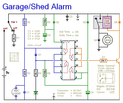
This is a basic single-zone burglar alarm circuit. Its features include automatic exit and entry delays, as well as an optional siren cut-off timer. It has an extremely low standby current, making it ideal for battery-powered operation. This circuit...
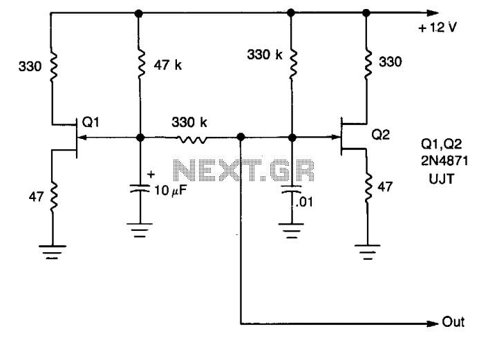
A low-frequency oscillator (Q1) modulates a high-frequency oscillator (Q2) along with its associated timing capacitor. The output frequency varies continuously. The circuit comprises two primary components: the low-frequency oscillator (Q1) and the high-frequency oscillator (Q2). The low-frequency oscillator is responsible...
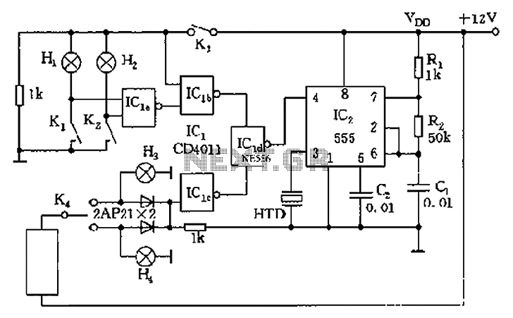
The circuit presented is a 555 timer-based alarm system for vehicles, which primarily consists of a 555 timer and a quad 2-input NAND gate configuration. It is designed to produce a long beep sound when oil pressure is low...
Warning: include(partials/cookie-banner.php): Failed to open stream: Permission denied in /var/www/html/nextgr/view-circuit.php on line 713
Warning: include(): Failed opening 'partials/cookie-banner.php' for inclusion (include_path='.:/usr/share/php') in /var/www/html/nextgr/view-circuit.php on line 713