
Photoelectric Sensor Circuit
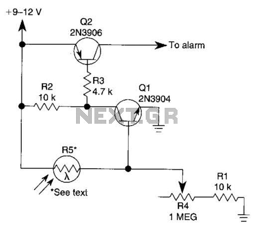
The described circuit operates as a non-contact intrusion detection system utilizing a light-dependent resistor (LDR) for light sensing. The LDR (R5) plays a critical role in the functionality of the circuit. When exposed to sufficient light, the resistance of R5 decreases significantly, allowing current to flow to the base of Q1, a general-purpose NPN transistor. This transistor, when activated, conducts and pulls its collector voltage close to ground, thus affecting the operation of the subsequent transistor, Q2.
Transistor Q2, a 2N3906 PNP type, is configured in such a way that it acts as a switch for powering the alarm circuit. When Q1 is in saturation, it effectively pulls the base of Q2 low, turning it on. In this state, the collector of Q2 is connected to the positive supply voltage, allowing current to flow through the alarm system, which may include a buzzer or a siren, thus notifying of the intrusion.
The circuit's design allows for a high degree of sensitivity and reliability in detecting intrusions. The use of an LDR provides a simple yet effective means of detecting changes in light levels, which is crucial for the operation of the alarm system. The transition from a closed to an open circuit state upon interruption of the light path ensures that the system can promptly respond to unauthorized access attempts, making it suitable for various security applications.
Overall, the integration of the LDR with the transistor switching mechanism forms a robust detection system that can be easily implemented in a variety of security setups, offering an effective solution for intruder detection without the need for physical contact. The circuit can be used as a sensor that can trigger an alarm, without direct contact being made by the intruder. In this circuit, a visible or invisible light source radiates on the sensor, keeping the detection loop in what could essentially be called a normally closed condition.
As long as the light source striking R5 remains uninterrupted, the switch remains closed. But if an intruder passes between the light source and the sensor, the circuit goes from closed to open, and triggers the alarm. A light-dependent resistor (LDR), whose resistance varies inversely in with the amount of light hitting its sensitive surface, is used.
A bright light aimed at R5 causes its internal resistance to drop as low as a few hundred ohms; in total darkness, the unit`s resistance can rise to several megohms. The light-dependent resistor (R5) is connected between the +Vsupply and the base of Ql. As long as R5 detects light, it supplies ample base current to cause Ql`s collector to saturate to near ground level.
That also pulls the base of Q2 (a 2N3906 general-purpose pnp transistor) to near ground level, turning it on and clamping its collector to the + V rail. 🔗 External reference
Related Circuits

This alarm circuit is designed to monitor a mains-powered smoke detector located in a shed used for dog kennels. It ensures complete isolation from the mains, allowing low-voltage (12V) cabling to connect to the alarm circuit situated inside the...
This circuit is designed to demonstrate high frequency and high voltage, capable of producing approximately 30kV, depending on the transformer utilized. It is cost-effective and straightforward to construct, primarily using a standard TV flyback transformer. This circuit can power...

The popularity and easy access of RS-232 ports lend them to many communication projects. You can use a port as is or as a tiny parallel port when the exchange uses only control lines. Before the asynchronous serial-data transfer...

The Air Flow Sensor Circuit describes sensing air flow using the microcontroller PIC16C781. Air flow is detected by the cooling effect of air. The Air Flow Sensor Circuit utilizes the PIC16C781 microcontroller to effectively measure air flow by leveraging the...

This design circuit is for a simple 27MHz transmitter that produces a carrier signal. The circuit generates an unmodulated 27MHz signal, which can be received by a compatible receiver. The transmitter operates as a basic crystal oscillator, with the...
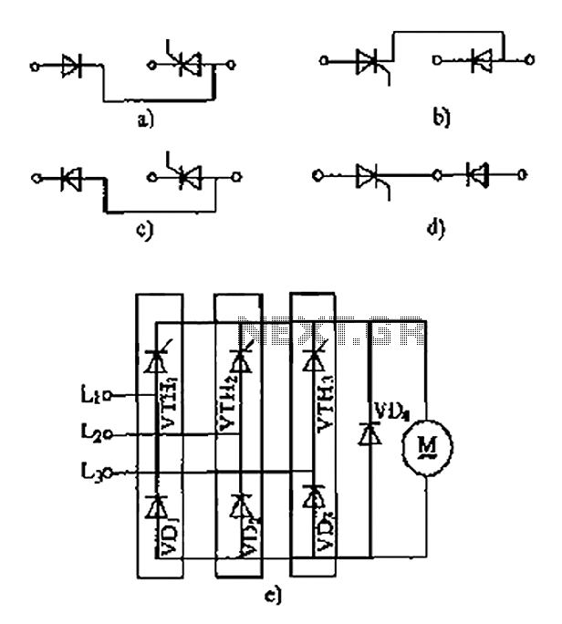
The thyristor linking arm rectifier module is a three-phase half-controlled bridge rectifier circuit. The thyristor-rectifier module linking arm consists of a thyristor and a rectifier diode connected in series or parallel, designed to fulfill specific requirements in power circuits....
Warning: include(partials/cookie-banner.php): Failed to open stream: Permission denied in /var/www/html/nextgr/view-circuit.php on line 713
Warning: include(): Failed opening 'partials/cookie-banner.php' for inclusion (include_path='.:/usr/share/php') in /var/www/html/nextgr/view-circuit.php on line 713