
IC Controlled Emergency Light with Charger Circuit Schematic Free With Explanation
The integrated circuit controlled emergency light circuit is designed for reliability and efficiency in power management during mains failure. The NE555 timer, configured in astable mode, generates a continuous square wave output, which is crucial for driving the MOSFETs that control the inverter section. This configuration allows for effective conversion of the DC battery voltage to an AC output suitable for powering standard fluorescent lighting.
The use of a push-pull amplifier configuration with MOSFETs T3 and T4 enhances the circuit's efficiency, allowing for higher output power while minimizing heat generation. The selection of a transformer (X2) that can handle the required voltage and power ratings ensures that the circuit can operate safely and effectively under load conditions.
The overcharge protection mechanism is critical for maintaining battery health and longevity. The LM308 comparator monitors the battery voltage continuously, providing a feedback loop that prevents overcharging. By utilizing a zener diode to set a precise reference voltage, the circuit can accurately determine when to stop charging the battery, thereby preventing damage due to excessive voltage.
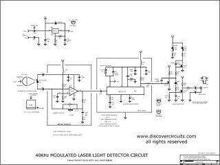
Overall, this emergency light circuit effectively combines automatic operation, power management, and safety features, making it suitable for various applications where reliable lighting is necessary during power outages. Proper thermal management of the MOSFETs is essential; therefore, adequate heat sinks must be used to ensure that the components operate within safe temperature limits.The circuit shown here is that of the IC controlled emergency light. Its main features are: automatic switching-on of the light on mains failure and battery charger with overcharge protection. When mains is absent, relay RL2 is in deenergised state, feeding battery supply to inverter section via its N/C contacts and switch S1.
The inverter section comprises IC2 (NE555) which is used in stable mode to produce sharp pulses at the rate of 50 Hz for driving the MOSFETs. The output of IC3 is fed to gate of MOSFET (T4) directly while it is applied to MOSFET (T3) gate after inversion by transistor T2.
Thus the power amplifier built around MOSFETs T3 and T4 functions in push-pull mode. The output across secondary of transformer X2 can easily drive a 230-volt, 20-watt fluorescent tube. In case light is not required to be on during mains failure, simply flip switch S1 to off position. Battery overcharge preventer circuit is built around IC1 (LM308). Its non inverting pin is held at a reference voltage of approximately 6. 9 volts which is obtained using diode D5 (1N4148) and 6. 2-volt zener D6. The inverting pin of IC1 is connected to the positive terminal of battery. Thus when mains supply is present, IC1 comparator output is high, unless battery voltage exceeds 6. 9 volts. So transistor T1 is normally forward biased, which energises relay RL1. In this state the battery remains on charge via N/O contacts of relay RL1 and current limiting resistor R2. When battery voltage exceeds 6. 9 volts (overcharged condition), IC1 output goes low and relay RL1 gets deenergised, and thus stops further charging of battery.
MOSFETs T3 and T4 may be mounted on suitable heat sinks. 🔗 External reference
Related Circuits

The circuit is designed to regulate a dual power supply that provides +12V and -12V from the AC mains. Such a power supply is an essential tool for an electronic hobbyist's workbench. The schematic of the circuit includes components...
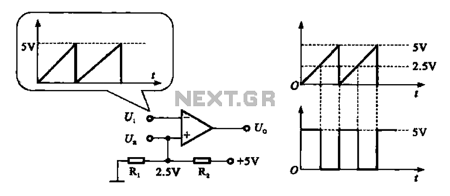
The addition and subtraction functions of an operational amplifier are facilitated through an external feedback network, which places the integrated operational amplifier in a deep state of negative feedback. In this linear region, the relationship between input and output...
The electronic pest-killing lamp circuit comprises an oscillator, control circuit, high voltage generator, LED indicator circuit, and power supply circuit. The schematic diagram illustrates these components. The oscillator circuit includes a time-base integrated circuit (IC), resistors R5 to R7,...

12V NiCad battery charger with a 200mA/h power supply. Refer to the specified page for an explanation regarding the related circuit diagram. The circuit for a 12V NiCad battery charger designed to supply a current of 200mA/h typically includes several...
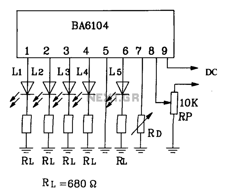
BA6104 is a five-digit LED level meter driver integrated circuit (IC) that features a basic application circuit. The input stage employs a PNP transistor with a composite base input, resulting in high input impedance. The output stage is configured...
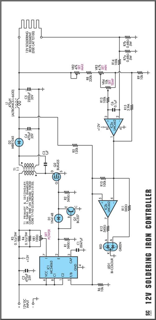
One reason commercial soldering stations are expensive is that they generally require soldering irons with built-in temperature sensors, such as thermocouples. This circuit eliminates the need for a special sensor by sensing the temperature of a soldering iron heating...