
IC fluorescent dimming considerations
The electronic ballast circuit for fluorescent dimming applications is designed to efficiently manage the power requirements of fluorescent lamps while providing the flexibility to dim the light output. This is crucial for applications in residential, commercial, and industrial settings where energy savings and extended lamp life are desired. The circuit begins with the rectification of the AC mains voltage, which is then filtered to produce a stable DC voltage. This DC voltage is essential for the operation of the half-bridge inverter, which converts the DC back into a high-frequency AC signal suitable for driving the fluorescent lamp.
The half-bridge inverter is composed of two switching devices that alternate their conduction states, creating a square wave output. This output is fed into the resonant tank circuit, which typically consists of an inductor and a capacitor. The resonant tank circuit is crucial because it shapes the output waveform into a sinusoidal form, which is necessary for the proper operation of the fluorescent lamp. The sinusoidal waveform ensures that the lamp operates efficiently and reduces the risk of flickering or other undesirable effects.
Dimming functionality is achieved through a feedback mechanism that continuously monitors the lamp current. By adjusting the duty cycle of the half-bridge inverter, the average power delivered to the lamp can be modified, allowing for smooth transitions between different brightness levels. The control IC, such as the IRS2530D, plays a vital role in this process by processing the feedback signals and adjusting the switching signals accordingly.
In addition to providing dimming capabilities, the circuit includes several protection features to enhance reliability. These features safeguard against conditions such as open filaments, failure to ignite, and brown-out situations. By incorporating these protective measures, the circuit minimizes the risk of damage to the lamp and the ballast itself.
Overall, the design of the electronic ballast circuit for fluorescent dimming applications reflects a careful balance between performance, efficiency, and reliability, making it suitable for a wide range of lighting applications. The integration of advanced control ICs and feedback mechanisms allows for precise control over the lamp operation, ensuring optimal performance and longevity.This article provides an overview of fluorescent dimming and an application circuit for low-end small fixture applications ICs where dimming levels below 10% are required and more comprehensive protection features are needed. The electronic ballast circuit block diagram (see Fig. 1) includes the ac-line input voltage (typically 220 Vac/50 Hz or 12 0 Vac/60 Hz), an EMI filter to block circuit generated switching noise, a rectifier and smoothing capacitor for ac to dc conversion, a control IC and half-bridge inverter for dc to high-frequency ac conversion, and the resonant tank circuit to ignite and run the lamp. The additional circuit block required for dimming is also shown that includes a dimming reference signal, a lamp current sensing and feedback signal, and a summing circuit for closed-loop control of the lamp current.
The lamp requires a current to preheat the filaments, a high-voltage for ignition, and a high-frequency ac current during running. To fulfill these requirements, the electronic ballast circuit first performs a low-frequency ac/dc conversion at the input, followed by a high-frequency dc-to-ac conversion at the output.
The ac mains voltage is full-wave rectified and then peak-charges a capacitor to produce a smooth dc bus voltage. The dc bus voltage is then converted into a high-frequency, 50% duty-cycle, ac square-wave voltage using a standard half-bridge switching circuit.
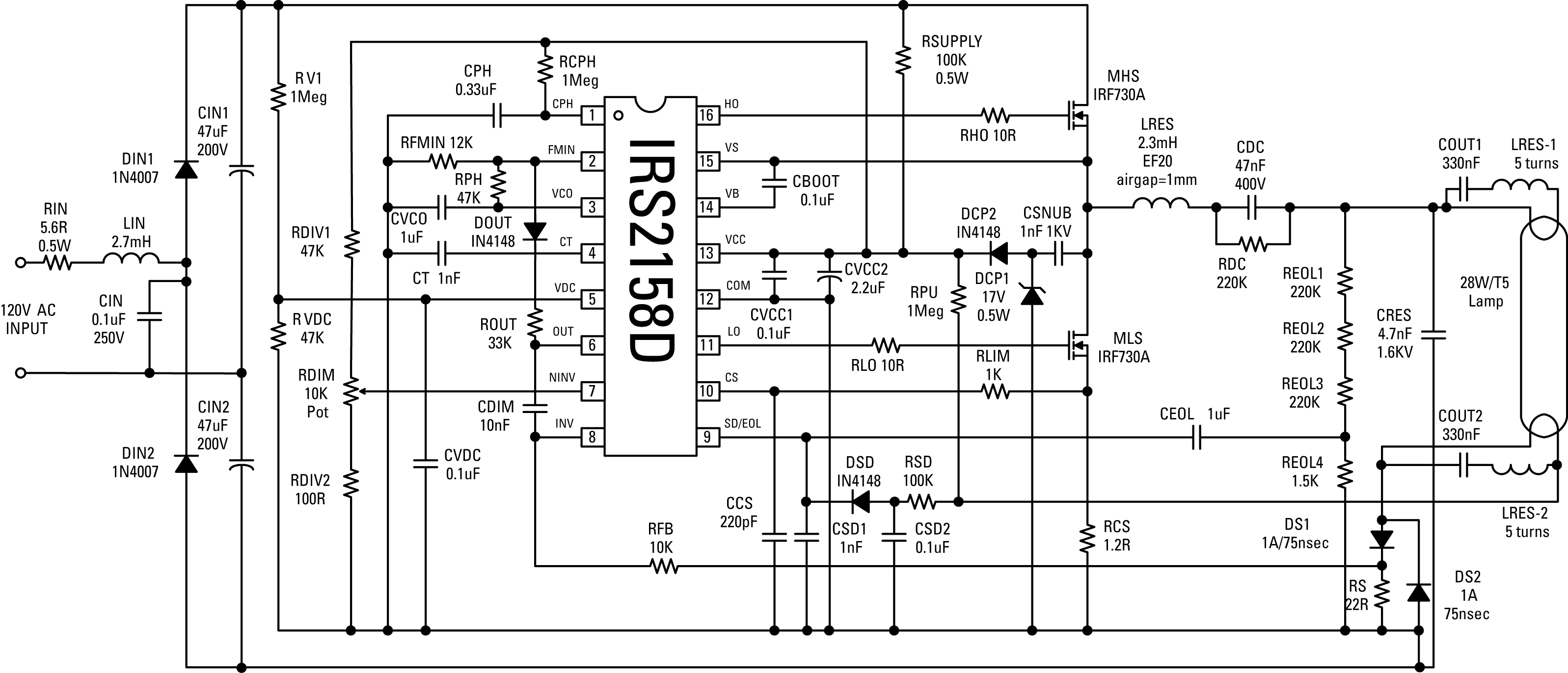
The high-frequency ac square-wave voltage then drives the resonant tank circuit and becomes filtered to produce a sinusoidal current and voltage at the lamp. The complete schematic is shown in Fig. 2. The 220-Vac/50-Hz line input voltage is full-wave rectified (BR1) and then goes through the EMI filter (CF and LF) before being smoothed by the dc bus capacitor (CBUS).
The half-bridge switches (MHS and MLS) are controlled by the IRS2530D DIM8 IC for preheating, igniting and dimming the lamp. RVCC1 and RVCC2 provide the micro-power start-up current for the VCC supply of the IC, and the charge pump (CSNUB, DCP1, and DCP2) takes over as the IC supply once the half-bridge begins to oscillate.
The resonant tank circuit (LRES and CRES) provides the necessary transfer function for generating high voltages for lamp ignition and low-pass filtering for dimming. A dc-blocking capacitor (CDC) ensures that the lamp current is always ac to prevent mercury migration which can cause lamp end blackening and a shortened lamp life.
Secondary windings from the resonant inductor (LRES:A, B) are used to heat the lamp filaments during preheat and dimming, and also separate the lamp current from the filament current allowing for a single current-sensing resistor (RCS) to be used to sense the lamp current. The ac lamp current measurement across RCS is coupled to the DIM pin through a feedback capacitor and resistor (CFB and RFB).
A potentiometer dimming input circuit is used (PDIM, RMIN, RMAX) to convert the potentiometer resistance to the necessary dimming reference voltage for the IC that is connected to the DIM pin. Finally, resistors RLMP1 and RLMP2 are used to detect if the lamp has been removed and to automatically restart the ballast when the lamp is re-inserted.
Protection against all other ballast fault conditions such as failure to strike, open filament, and low ac line/brown-out, are included internally to the IRS2530D to further reduce component count and increase reliability. The measured ballast waveforms are shown in Fig. 3. Figure 3a shows the VCO pin voltage (upper trace), lamp voltage (middle trace) and lamp current (lower trace) during normal preheat, ignition and dimming modes.
The VCO pin and lamp voltage ramp up during preheat and ignition to preheat the lamp filaments and then to ignite the lamp when the lamp ignition voltage threshold is reached. Lamp current starts to flow immediately after ignition at the start of dimming. Figures 3b and 3c show the half-bridge output voltage (VS pin, lower trace) together with the DIM pin voltage (upper trace) during 100% and 10% dimming conditions.
The DIM pin voltage amplitude decreases (together with the lamp current) from 100% down to 10% and the operating frequency is continuously adjusted to keep the valley of the sinusoid regulated at COM. A linear dimming ballast for a single 28W/T5 fluorescent lamp is shown (see Fig. 4) that is designed around the IRS2158D ballast control IC. This part incorporates fixed frequency preheat, regulated ignition, lamp fault and end of life protection circuitry that covers all failure modes, as well as auto-restart when the lamp is removed and replaced.
In addition a low-offset operational amplifier is included, which is used in this design to implement lamp dimming by frequency modulation. The lamp arc current is fed back and compared with a control voltage derived from a potentiometer (RDIM).
The upper and lower dimming limits are bounded by the resistors RDIV1 and RDIV2. The op-amp output produces an error voltage, which is connected to the FMIN pin through a diode and by sinking more current from the FMIN pin, it causes the frequency to be increased, which in turn reduces the lamp power. Stability is achieved by optimizing the response time of the control loop by correct selection of capacitor CDIM.
The value of this is likely to vary depending on the particular lamp that is being dimmed. The measured ballast waveforms are shown in Fig. 5. Figure 5a shows the lamp voltage (upper trace) and CPH pin (lower trace) during normal preheat, ignition and running modes. Fig. 5b shows the lamp current (upper trace, black), lamp voltage (upper trace, blue) and the half-bridge output node (lower trace, green) during 100% dimming.
Figure 5c shows the lamp current (upper trace, black), lamp voltage (upper trace, blue) and the half-bridge output node (lower trace, green) during 5% dimming. The IRS2530D DIM8 IC includes all of the necessary functions for smooth dimming and protection against fault conditions.
The dimming mini-ballast circuit provides excellent performance in fewer than 35 components. The small 8-pin package together with low component count allows for the complete design to be realized in a small mini-ballast form factor. The IRS2158D offers additional programmability to the designer such as the oscillator frequency range and dead-time, and includes a non-dedicated, low-offset op amp.
The IRS2158D also includes an additional end-of-life protection feature that is mandatory for T5 lamps. To adjust either circuit for different lamp types, power levels or line input voltages, International Rectifier offers a Ballast Design Assistant (BDA) software program to help designers get their ballast designs working on the bench quickly.
This program allows the user to select from different line input voltage ranges, lamp types and lamp configurations, and then generates necessary ballast output data, IC programmable component values, inductor specifications, and the complete schematics and bill of materials. – 🔗 External reference
Related Circuits
Have you verified whether you can see the zero crossings on your input pin? It may be beneficial to write a sketch that toggles the LED on pin 13 every 50 or 60 zero crossings. This should result in...

Several individuals have struggled to locate the transformer necessary for the Black Light project. Consequently, an investigation was conducted to identify a fluorescent lamp driver that does not necessitate any specialized components. A suitable option was discovered in Electronics...
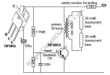
A 40-watt fluorescent tube lamp or two 20-watt tubes in series will be driven by this circuit. The transformer is wound on a ferrite rod with a diameter of 10 mm and a length of 8 cm. The circuit described...
This circuit originates from a 14-watt commercial electric spiral bulb from Home Depot. The layout is commendable and credit is due to Sam Goldwasser for its design. The circuit features an interesting oscillator configuration, which will be explained in...
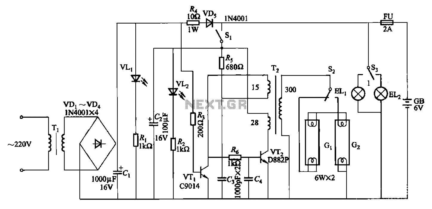
The 786A multi-functional double-tube fluorescent emergency circuit is illustrated in Figure 2-129. This circuit shares similarities with Figure 2-125. The 786A multi-functional double-tube fluorescent emergency circuit is designed to provide illumination during power outages or emergencies. It utilizes two fluorescent...
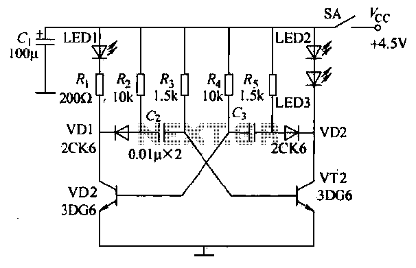
The infrared transmitter circuit, as depicted in Figure 18-la, utilizes transistors VT1 and VT2 along with RC components to create an astable multivibrator. The circuit operates with VT1 and VT2 receiving base bias from resistors, and closing switch SA...