
IC rprecision waveform generator with sweep and frequency modulation

The described circuits are designed to facilitate frequency modulation (FM) and sweep modulation, providing flexibility in signal generation for various applications. Circuit 5-50A is specifically tailored for FM applications, allowing for slight frequency deviations, typically around ±10%. This circuit is suitable for applications where maintaining a stable carrier frequency with minor fluctuations is essential, such as in communication systems where signal integrity is crucial.
Circuit 5-50B offers a more extensive sweep range of 1000:1, making it ideal for applications that require a broad frequency range modulation. The modulation characteristics are influenced by the voltage applied to pin 8, where a higher voltage (equal to VCC) results in a sweep frequency that approaches 0 Hz. Conversely, as the voltage at pin 8 decreases to the limit defined by VCC - (1/3 VSUPPLY - 2), the sweep frequency reaches its maximum value. This relationship allows for precise control over the modulation frequency, enabling the user to tailor the circuit's performance to specific requirements.
To enhance waveform symmetry and minimize distortions, it is recommended to incorporate a 10-MΩ resistor between pins 5 and 11. This addition helps balance the circuit's output, ensuring that the generated waveforms maintain a consistent shape and amplitude, which is particularly important in high-fidelity applications. The integration of this resistor can significantly improve the overall performance of the circuit, making it a valuable modification for users seeking optimal results in their FM or sweep modulation needs.These circuits are similar to that of Fig. 5-47, except that the circuits provide for FM or sweep modulation. Use circuit 5-50A for FM (small deviations, about ±10%). Use circuit 5-50B for a sweep range of 1000:1. As a guideline, the sweep frequency approaches 0 Hz when the voltage at pin 8 equals VCC, and reaches maximum at the lower pin-8 voltag e limit of VCC - (1/3 VSUPPLY -2). Waveform symmetry variations can be minimized when a 10-M resistor is added between pins 5 and 11. 🔗 External reference
Related Circuits
The circuit under discussion is a four-siren sound generator utilizing the UM3561 integrated circuit (IC), which is a low-power CMOS device. Four distinct sounds can be generated by activating switches S1, S2, and S3. This circuit is versatile and...
The circuit utilizes a 555 timer configured as a multivibrator, where the oscillation frequency is determined by resistors R1, R2, and capacitor C1. The frequency formula is given by fo = 1.443 / ((R1 + R2) * C1). The...
This circuit is designed to demonstrate high frequency and high voltage, capable of producing approximately 30kV, depending on the transformer utilized. It is cost-effective and straightforward to construct, primarily using a standard TV flyback transformer. This circuit can power...
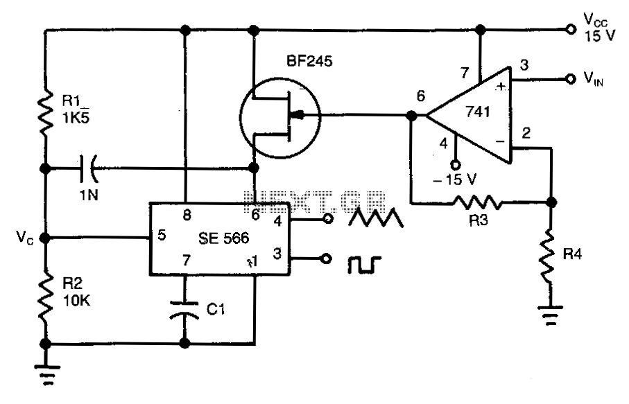
This circuit operates based on the frequency variation of the function generator in relation to the input voltage (ViN). The frequency is influenced by the capacitance and resistor connected to pin 6, with the resistor being substituted by a...
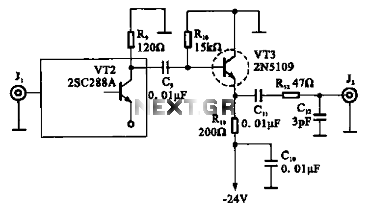
A high-frequency signal is displayed in the output amplifier. The circuit consists of a VI3 common collector amplifier (emitter follower) designed to enhance the child-band. It is a high-frequency amplifier (1-250 MHz) that increases the output voltage and boosts...

Noise level measured into 75ohm 3.1kHz BW using Siemens D2006 level meter: -80dBU (77.5mV) from zero to 1MHz and drops 3dB on 17MHz. Decrease the first coupling capacitor (68nF) to 10nF to increase the lower limit to 50kHz. The...