
Flicker frequency of multiple sets of different light-emitting diode lights chain circuit
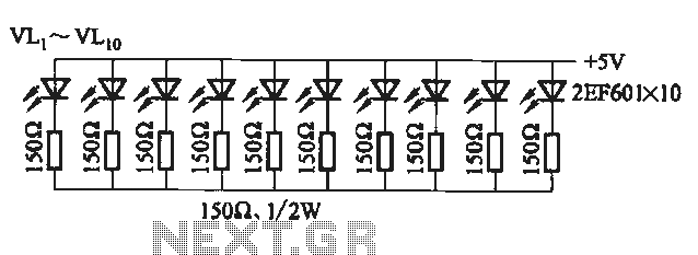
The described circuit is a versatile application of the 555 timer IC, operating in astable mode to generate a continuous pulse output. The oscillation frequency is critically dependent on the values of R1, R2, and C1, which dictate the timing characteristics of the circuit. The formula for the frequency fo illustrates that as the resistance values or capacitance increase, the frequency decreases, resulting in a longer pulse duration.
In this configuration, the output from the 555 timer is fed into multiple control transistors (VT1 to VT4). Each transistor acts as a switch that can either allow current to flow through its corresponding light-emitting diode (LED) group or cut off the current, thus controlling the illumination of groups A, B, C, and D. This switching mechanism allows for dynamic control of the LEDs, enabling various lighting patterns or sequences based on the frequency and duty cycle of the output signal.
The circuit can be further enhanced by incorporating additional features such as variable resistors for R1 and R2, allowing for adjustable frequency and duty cycle. Additionally, the use of different types of LEDs can create diverse lighting effects, making this circuit suitable for applications in decorative lighting, indicators, or visual displays. Proper heat dissipation measures should be considered for the transistors depending on the current requirements of the LED groups to ensure reliable operation.It uses multi-vibrator 555 consisting of an integrated circuit, the oscillation frequency Ri, the R2 and Cl decisions (such as group A), fo = 1. 443 / (RI + R2) Cl. By the pulse signal Ai-A4 3-pin output control transistor VTi-VT4 conduction and off, control the light emitting diode groups namely A, B, C, D of turning on and off.
Related Circuits
Measurements were conducted using a modified program to measure the voltage applied at the drive electrode and the voltage at the sense electrode. Conductance was calculated using the formula 0.01S * V_resist / (V_applied * V_resist). The initial version...
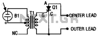
The photo strobe slave trigger circuit utilizes a solar cell and a silicon-controlled rectifier (SCR) to activate any strobe light when triggered by a master strobe. The small solar cell generates a minimal voltage when illuminated. The photo strobe slave...

This circuit is a system designed to generate a pulsed modulation signal for a Gunn diode microwave oscillator. It features several preset speed settings (S3 a and b). A 555 timer is employed in conjunction with a frequency divider...
The frequency jammer operates by generating interfering RF noise centered around a 2.45 GHz carrier frequency. As the power of this noise increases, the signal-to-noise ratio of the wireless communication channel decreases, leading to a higher bit error rate...
This light sensor switch circuit enables the automatic activation of a lamp when ambient light levels are low (such as during nightfall) and keeps the lamp illuminated for a specified duration. When transistors T4 and T5 are activated, the...
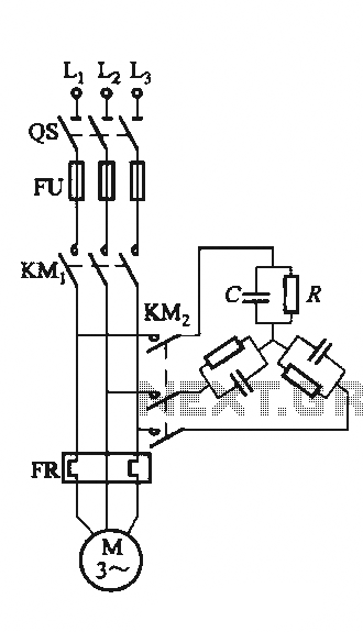
The circuit illustrated in Figure 3-151 consists of capacitor banks arranged in a specific configuration. Figure 3-151 (a) depicts capacitor banks connected in a shaped configuration, which is suitable for shaped or Y-connected motors. Figure 3-151 (b) shows Y-connected...
Warning: include(partials/cookie-banner.php): Failed to open stream: Permission denied in /var/www/html/nextgr/view-circuit.php on line 713
Warning: include(): Failed opening 'partials/cookie-banner.php' for inclusion (include_path='.:/usr/share/php') in /var/www/html/nextgr/view-circuit.php on line 713