
IC Voltage Regulators-withCircuit - Design & Theory
IC voltage regulators are essential components in electronic circuits, providing stable output voltages from a varying input voltage source. They can be categorized into several types, including linear regulators, fixed regulators, adjustable regulators, and switching regulators.
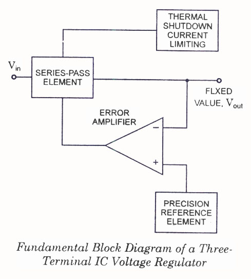
Linear voltage regulators maintain a constant output voltage by using a feedback mechanism to adjust the resistance within the circuit. The block diagram typically illustrates the input voltage, the regulator, and the output voltage, along with feedback paths. Fixed voltage regulators provide a predetermined output voltage, while adjustable voltage regulators allow for output voltage customization through external resistors.
Switching voltage regulators, on the other hand, utilize a different principle. They convert the input voltage to a high-frequency square wave and then use inductors, capacitors, and diodes to filter and smooth the output. This method is more efficient than linear regulation, especially for applications requiring significant power conversion.
The circuit diagrams for these regulators vary based on their design and application. For linear regulators, the schematic often includes a pass transistor, input and output capacitors, and a feedback network. Fixed regulators feature a simpler design, while adjustable regulators incorporate additional components for voltage setting. Switching regulators are more complex, showcasing components like inductors, diodes, and control ICs.
Understanding the differences and applications of these voltage regulators is crucial for designing reliable and efficient electronic systems. Each type serves specific needs, whether it be low dropout voltage in linear regulators or high efficiency in switching regulators, making them indispensable in modern electronics.IC Voltage Regulators -Circuit diagram & Block diagram of Linear,Fixed, Adjustable (positive & negative) & Switching voltage regulators.. 🔗 External reference
Related Circuits
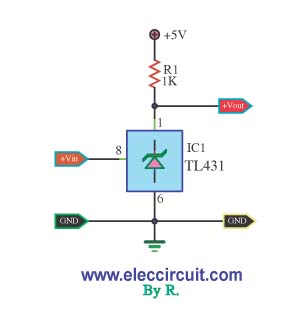
This is a simple pressure level check circuit, utilizing the integrated circuit TL431. It operates with a power supply of 5 volts for the digital circuit. The general feeding signal is... The circuit is designed to monitor pressure levels by...
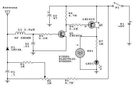
This electronic RF detector project is constructed using common transistors and a few standard electronic components. The RF detector is capable of responding to RF signals below the standard broadcast band and extending to over 500 MHz, providing both...
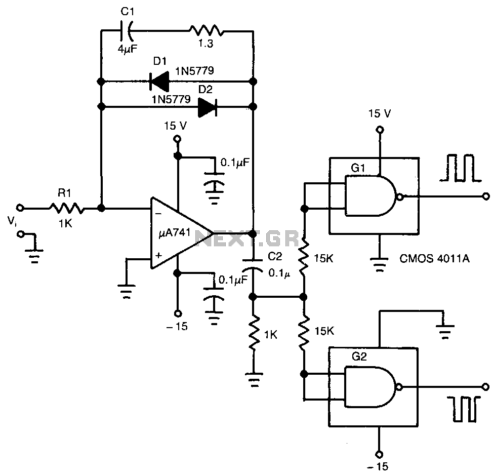
The input voltage, V1, causes capacitor C1 to charge, producing a ramp voltage at the output of the 741 operational amplifier. Diodes D1 and D2 are four-layer devices. When the voltage across C1 reaches the breakover voltage of either...
A voltage-to-frequency converter (VFC) circuit is illustrated in the schematic diagram below. The circuit utilizes a 555 integrated circuit (IC) as the central component of its operation. The voltage-to-frequency converter (VFC) is a crucial electronic circuit that converts an input...
A zero-crossing detector converts an input sine wave (Vin) into a square wave, which, when high, charges an op-amp integrator. A reference-input square wave subsequently discharges the integrator. The output voltage of the integrator at the end of this...
This is a reproduction of the filter circuit and microphone windshield design mentioned in the article "Wildlife Recording In Stereo" by David J. Tombs, published in 1974. The filter circuit and microphone windshield design outlined in the referenced article are...
Warning: include(partials/cookie-banner.php): Failed to open stream: Permission denied in /var/www/html/nextgr/view-circuit.php on line 713
Warning: include(): Failed opening 'partials/cookie-banner.php' for inclusion (include_path='.:/usr/share/php') in /var/www/html/nextgr/view-circuit.php on line 713