2 Transistor FM Voice Transmitter
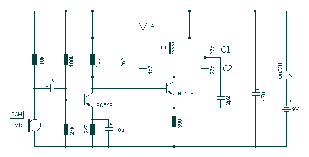
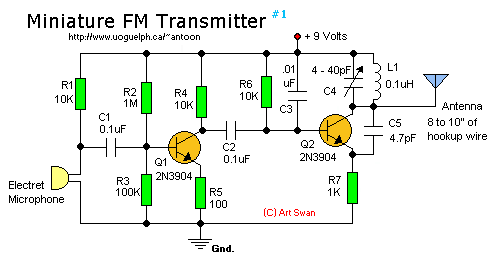
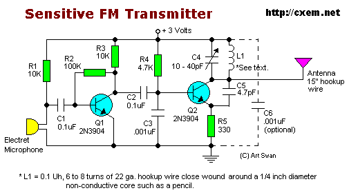
Take care with transmitter circuits. It is illegal in most countries to operate radio transmitters without a license. Although only low power this circuit may be tuned to operate over the range 87-108MHz with a range of 20 or 30 metres. More: I have used a pair of BC548 transistors in this circuit. Although not strictly RF transistors, they still give good results. I have used an ECM Mic insert from Maplin Electronics, order code FS43W. It is a two terminal ECM, but ordinary dynamic mic insert.
The described circuit is a low-power FM transmitter designed to operate within the FM broadcast band of 87-108 MHz. It is essential to note that operating such a transmitter without a proper license may contravene legal regulations in many jurisdictions. The circuit utilizes a pair of BC548 transistors, which, while not specifically categorized as RF transistors, are capable of providing satisfactory performance for this application due to their transistor characteristics, including low noise and sufficient gain.
The BC548 transistors are configured in a common-emitter amplifier arrangement, which is conducive to amplifying the audio signals captured by the microphone. The ECM microphone insert serves as the audio input transducer, converting sound waves into electrical signals. The microphone's two-terminal configuration allows for simple integration into the circuit, where one terminal is connected to the ground and the other to the base of the first transistor.
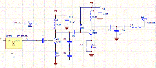
The circuit is designed to modulate the audio signal onto the carrier frequency, which is determined by the component values in the tank circuit, typically formed by a combination of inductors and capacitors. This tank circuit is crucial for tuning the transmitter to the desired frequency within the FM band. The output stage of the circuit is likely to include a simple LC matching network to ensure efficient power transfer to the antenna, which can significantly affect the transmission range, estimated to be around 20 to 30 meters under optimal conditions.
Overall, while the circuit may be relatively straightforward and low in power consumption, it is imperative to respect local regulations regarding the operation of radio transmitters to avoid legal repercussions.Take care with transmitter circuits. It is illegal in most countries to operate radio transmitters without a license. Although only low power this circuit may be tuned to operate over the range 87-108MHz with a range of 20 or 30 metres. I have used a pair of BC548 transistors in this circuit. Although not strictly RF transistors, they still give good results. I have used an ECM Mic insert from Maplin Electronics, order code FS43W. It is a two terminal ECM, but ordinary dynamic mic insert 🔗 External reference
