
TRIAC Switch To Control High-Voltage Devices
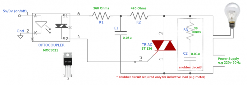
In the ON condition, when 5V is supplied to pins 1 and 2 of the opto-coupler (MOC3021), an internal connection is established between pins 6 and 4, allowing current to flow. This connection provides gate current to the TRIAC (pin 3), causing the TRIAC to conduct the main current between pins 2 and 1, thus completing the circuit and illuminating the bulb.
Additional components include:
- Resistors: R1 (360 Ohms, 1W), R2 (470 Ohms, 1W), R3 (39 Ohms, 1W, optional for inductive loads)
- Capacitors: C1 (0.05uF, 400V, non-electrolytic), C2 (0.01uF, 400V, non-electrolytic, optional for inductive loads)
- TRIAC: BT136
- Integrated Circuit: IC1 MOC3021 (opto-coupler)
- Miscellaneous: 220V bulb as load, PCB or breadboard, flexible wire, soldering rod, etc.
When 0V is applied to the opto-coupler, it opens the electrical connection between pins 6 and 4, preventing current flow. Consequently, the gate current to the TRIAC is halted, stopping the main current between pins 2 and 1, which turns off the bulb. This switching mechanism can control both AC and DC devices, provided that the appropriate power supply is used.
It is crucial to note that the snubber circuit is only necessary for inductive loads (such as motors). For non-inductive loads, C2 and R3 can be omitted from the circuit. Selecting a TRIAC with a suitable current rating is important; this circuit can support devices that draw up to 4A of current.
The advantages of this circuit include the ability to control a load device with a very low voltage of 3V to 5V. The opto-coupler ensures electrical isolation between high-voltage and low-voltage circuitry, preventing high voltage from flowing back to the microcontroller, thereby enhancing safety. Additionally, this design eliminates mechanical noise, occupies less space on a PCB, and allows for rapid switching, a capability that electromagnetic relays lack due to their mechanical operation.From ages electron-magnetic relays are being used as switches to control high voltage devices. But, because of their bulky size and noise (both electrical and mechanical) people started using TRIAC with opto-coupler as better alternative. Above circuit uses TRAIC and Opto-coupler to use small voltage to control high voltage devices. For example, micro-controller to control 220v bulb or any device which runs on high voltage. ON Condition : When 5v is applied to pin 1 & 2 of the opto-coupler (MOC3021), pin 6 & 4 gets connected internally(Within opto-coupler) and allows current to flow between them.
This connection provides GATE current to the TRIAC (TRIAC pin 3) and TRIAC starts conducting the main current between pin 2 & 1, which completes the circuit and makes bulb to glow. Resistors R1 (360 Ohms, 1W) R2 (470 Ohms, 1W) R3 (39 Ohms, 1W, optional : only for inductive load) Capacitor C1 (0.05uF, 400V, non electrolytic) C2 (0.01uF, 400V, non electrolytic, optional : only for inductive load) TRIAC TRIAC (BT136) Integrated Circuit IC1 MOC3021 (OPTO-COUPLER) Miscellaneous 220v bulb as load PCB or Breadboard Flexible Wire Soldering rod etc.. Now, when 0V is applied to opto-coupler, opto-coupler makes pin 6 & 4 electrically opened and doesn't allow any current to flow between them, as a result it stops the GATE current to TRIAC and the main current between pin 2 & 1 also stops, which finally turns off the bulb.
Both type of devices working on AC and DC can be controlled using this switch, provided proper power supply is used for them Important to note that the mentioned snubber circuit is only required if your load is inductive (like motor etc..). For non inductive loads you can just remove C2 & R3 from your circuit and leave it open. It is important to select proper current rating TRIAC, above circuit may support device which draws upto 4A of current.
Benefits of this circuit Very low voltage 3V to 5V can be used to control load device. Opto-Coupler maintains separation between high voltage and low voltage circuitry and never allows high voltage to flow back to micro-controller making it safe. No mechanical noise. Compact, occupies less volume on PCB. Can be used for fast switching, electromagnetic relays cannot due to mechanical make/break. 🔗 External reference
Related Circuits
The circuit utilizes relay control. The voice switch operates as follows: upon the first clap, the load (lights) is activated; upon the second clap, the load (lights) is deactivated. This system can be employed to control lighting in residential...

We have developed a powerful yet inexpensive and easy to construct experiment control system. The construction of the system together with the control software is described here. All circuits and software are free to download and use for nonprofit....
This is basically a Schmitt Trigger circuit which receives input from a cadmium sulfide photo cell and controls a relay that can be used to switch off and on a street lamp at dawn and dusk. I have built...

One-half of a 556 dual timer monitors the temperature of a liquid bath, controlling a heating element that maintains temperature within ±2°C over a 32° - 200°C range. The other half monitors the liquid level, disconnecting the heater when...
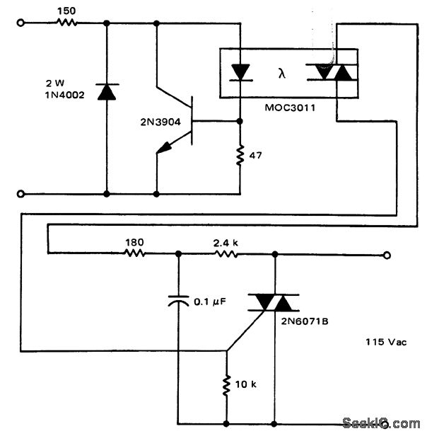
A solid-state relay circuit features an input protection mechanism utilizing the MOC3011 triac driver. The input voltage for the protection circuit can range from 3 to 30 volts DC, as noted by Motorola Semiconductor Products Inc. The solid-state relay (SSR)...
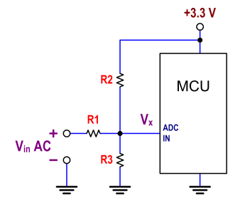
The ATtiny24 microcontroller's ADC is utilized to record an AC signal, which operates within a voltage range of 0 to 3.3V. A precision rectifier is employed to eliminate the negative portion of the signal. The circuit incorporates an LMC6484...