
Quadrature Sinewave Oscillator
The quadrature oscillator is commonly used in various applications such as signal processing, communications, and control systems. It operates on the principle of generating two sinusoidal outputs that are orthogonal to each other, which is essential for tasks like modulation and demodulation in communication systems.
Typically, a quadrature oscillator circuit may utilize operational amplifiers, resistors, and capacitors to achieve the desired phase shift between the output signals. The operational amplifiers are configured in a feedback loop that stabilizes the oscillation frequency while ensuring that the output signals maintain the required phase relationship.
In a standard configuration, the oscillator consists of two identical RC networks that are connected to the inverting and non-inverting inputs of the operational amplifiers. The phase shift introduced by these RC networks is crucial; each stage of the network contributes to the total phase shift, ultimately resulting in one output signal being delayed by 90 degrees relative to the other.
The frequency of oscillation can be determined by the values of the resistors and capacitors used in the circuit. By adjusting these components, the frequency can be fine-tuned to meet specific application requirements. Additionally, the output signals can be further processed or amplified depending on the intended use.
Overall, the quadrature oscillator serves as a vital component in various electronic systems, providing essential functionality where phase relationship and signal integrity are critical.Quadrature oscillator is another type of phase shift oscillator. This circuit produce two sine wave signal. One of them is shifted 90 degree from the other.. 🔗 External reference
Related Circuits
The following circuit is a basic 555 square wave oscillator. Features include a 1 kHz tone, simple circuitry, a current limit of 200 mA, reduced inductive voltage, and a supply voltage range of 4.5 to 9 volts. Components used...
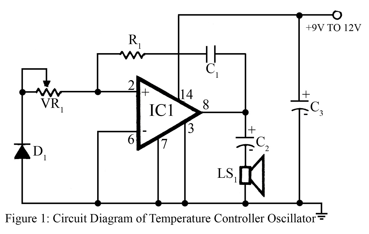
The output frequency or tone of this oscillator circuit varies with the temperature at which the input germanium diode is maintained. The reverse resistance of D1 ranges from 500 ohms to 10 k ohms when the temperature fluctuates between...
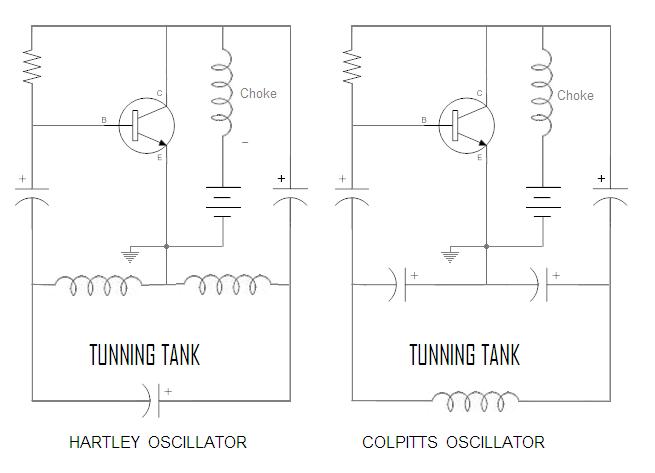
The circuit is a modified Colpitts oscillator, tuned with MV209 varactor diodes. The resonating inductor and the drain choke are selected by a rotary switch. 1N5711 Schottky diode, D, clamps the maximum positive voltage on the gate of oscillator...
More: A comprehensive electronic schematic is essential for understanding the functionality and design of electronic circuits. It typically includes various components such as resistors, capacitors, diodes, transistors, and integrated circuits, each represented by standardized symbols. The interconnections between these...

The AD9835 combines the Numerical Controlled Oscillator (NCO), COS Look-Up Table, Frequency and Phase Modulators, and a Digital-to-Analog Converter on a single integrated circuit. With more easy words you can say that this circuit is an oscillator where the...
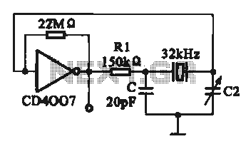
A 32 kHz clock oscillator is essential for digital circuits, as depicted in the schematic. The 32 kHz crystal clock oscillator serves to provide a time reference signal for the digital circuit. It utilizes a CMOS integrated circuit, specifically...
Warning: include(partials/cookie-banner.php): Failed to open stream: Permission denied in /var/www/html/nextgr/view-circuit.php on line 713
Warning: include(): Failed opening 'partials/cookie-banner.php' for inclusion (include_path='.:/usr/share/php') in /var/www/html/nextgr/view-circuit.php on line 713