
wein bridge oscillator

The Wien bridge oscillator is a type of electronic oscillator that generates sine waves. It utilizes a configuration of resistors and capacitors to establish the necessary phase shift for oscillation. The LM741 operational amplifier serves as the active element in this circuit, amplifying the signal and maintaining the oscillation.
In this specific configuration, the capacitors C1 and C2, each valued at 0.01 µF, are used to create a frequency-determining network. The resistors R1 and R2, both set at 3 kΩ, form a voltage divider that ensures the correct gain for the oscillator. The feedback resistor Rf, valued at 2 kΩ, and the resistor Ra, set at 1 kΩ, work together to stabilize the oscillation amplitude and allow for the automatic gain control characteristic of the Wien bridge oscillator.
The frequency of oscillation can be calculated using the formula:
\[ f = \frac{1}{2\pi R \sqrt{C_1 C_2}} \]
Where R is the resistance value of R1 and R2, and C1 and C2 are the capacitance values. Substituting the given values into the formula provides insight into the operating frequency of the oscillator.
It is essential to ensure that the LM741 is powered with appropriate supply voltages, typically ±15 V, to achieve optimal performance. Additionally, a light bulb or thermistor may be incorporated into the circuit to provide automatic gain control, allowing the oscillator to maintain a consistent amplitude despite variations in component tolerances or power supply fluctuations.
The final output waveform can be observed on an oscilloscope, demonstrating the sine wave characteristics typical of a Wien bridge oscillator. Proper layout and grounding techniques should be employed during the construction of the circuit to minimize noise and ensure stable operation.hello, i am doing a practical on lm 741. i want to make it to use it as an wein bridge oscillator.the value of c1=c2=0.01uF, R1=R2=3K, Rf=2k, Ra=1k.acc.. 🔗 External reference
Related Circuits
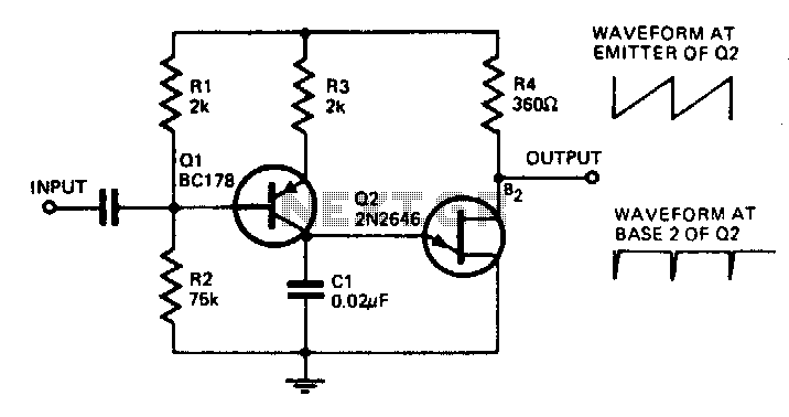
With the component values shown, the oscillator has a frequency of 8 kHz. When an input signal is applied to the base of Q1, the current flowing through Q1 is varied, thus affecting the time required to charge C1....
A quadrature oscillator is a type of phase shift oscillator that produces two sine wave signals, with one signal shifted by 90 degrees from the other. The quadrature oscillator is commonly used in various applications such as signal processing, communications,...
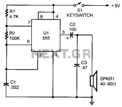
A 555 timer configured as an astable multivibrator is used in this circuit to generate an audio note. The capacitance value can be changed to vary the audio note as desired. The circuit utilizes a 555 timer IC, which...
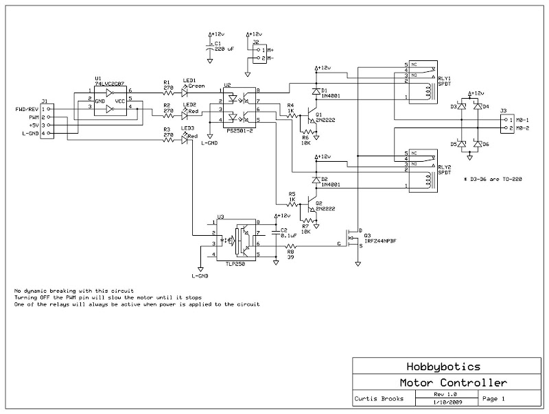
Develop a cost-effective high-current circuit that utilizes PWM. The design includes flyback diodes to protect the MOSFET from the back EMF generated by the motor when the power is switched on and off via the PWM signal. This configuration...
A crystal oscillator operates at a frequency of 51 MHz, which corresponds to the third harmonic of a 17 MHz fundamental frequency. Depending on the specific structure used, the drain-gate capacitance can be selected within a range of 0.5...
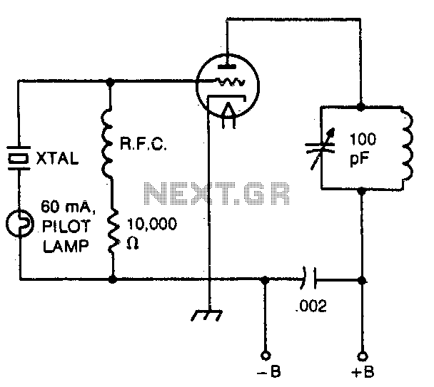
The pilot lamp limits current to prevent damage to the crystal. A very useful circuit. The circuit incorporates a pilot lamp designed to limit the current flowing to a crystal component, thereby safeguarding it from potential damage due to excessive...