
Impedance meter for Headphones


To use the FILVORA, connect a source of audio voice or music to the input jack J1. (I use the output jack of a transistor radio for my source.) Connect the plug of the mono headphone set or speaker to be measured to the output jack J2 of the FILVORA. Adjust the switch for the loudest volume. The correct setting indicates the average impedance. It can be very broad and somewhat hard to determine. Call it P2.
Rotate the switch in one direction from P2 for a small reduction in volume to position P1 (generally a two positions movement), then in the other direction from P2 by two positions to P3. If the volume at P1 and P3 are the same, P2 indicates the average impedance of the headset. If the volume at P1 and P3 is not the same, increment both the P1 and P3 settings ccw or cc by one position. When you obtain the same volume at the new P1 and P3 positions, you are done.
As stated above, the average headphone impedance is the calibration indication of the switch at point P2. Sometimes equal volume settings cannot be obtained with switch settings five positions apart. If this is the case, try to get equal volume settings four positions apart. If this is done, the average impedance is equal to the geometric mean of the settings of P1 and P3. (Take the square root of the product of the calibration readings at P1 and P3.)
Note: With magnetic elements, setting the switch to a high source resistance tends to emphasize the treble and reduce the bass response, compared to the response where the source matches the average impedance of the element. Setting the switch to a low resistance does the reverse. This setting rolls off the highs, and relatively speaking, emphasizes the bass. With ceramic or crystal elements, a high source resistance tends to emphasize the bass response. A low source tends to roll it off.
Determining a Personalized Headphone Impedance
If you are interested in DX reception with headphones and do not have normal hearing, you might want to customize the optimum source resistance for driving your headphones. This enables using the change in headphone frequency response as a function of headphone driving resistance to partially compensate your own hearing loss curve.
Input a voice signal and reduce its volume to a sufficiently low level such that you judge you understand about 50% of the words. Readjust the switch to see if you can obtain greater intelligibility at another setting. If you can, this new switch setting indicates the source resistance with which to drive your headphones to deliver maximum voice intelligibility for your ears. I call this resistance: Personalized Headphone Impedance (PHI).
Using a FILVORA with Hi-Fi Stereo Headphones If the unit connected to J2 is louder than the unit connected to J1, reverse the units. Now add attenuation in the path to the unit connected to J1 in 3 dB steps by using A1, A2 and A3 in the proper combinations (the dB's add), until the volume from the unit connected to J1 equals the volume in the unit connected to J2 as closely as possible. If the sound cannot be reduced to a low enough level because of volume control limitations in the INPUT source, use A4 to reduce the volume by 20 dB.
The sum of the dB settings of A1, A2 and A3 equals the difference in power sensitivity between the two headphones or speakers, independent of the impedance of the units. The settings of S1 and S2 indicate the average impedance of the two units (see part 1 for more details on this subject). The power insertion loss from jack J3 to either jack J1 or jack J2, with the attenuators set to zero, is 29dB.
Modifying the DFILVORA for Hi-Fi Stereo Headphones
To compare the power sensitivity of two stereo headphones, several modifications should be made to the DIFLVORA. J1 should be changed to a stereo jack, and the ring and tip connections tied together. The same change should be made to J2. This will cause each stereo headphone to be tested in mono mode with its elements connected in parallel.
The setting of switches S1 and S2 indicate the average impedance over the audio frequency range of two earphone elements in parallel, and that figure will be one-half the value of each element by itself. Also, the measurable range of individual element impedances will be changed from 10 - 100k Ohms to 20 - 200k. The range of impedance measurable for the parallel combo of two elements is still 10 to 100k Ohms. The circuit for the FILVORA has 12 resistance settings. It has a fixed input resistance of 1000 ohms about ±5%, no matter what load is connected the output or where the switch is set. The output resistance at any switch point is about ±5% of the value shown with any impedance driving the input. The insertion loss of the FILVORA is 26 dB. Standard 5% tolerance resistors are used.
To correct this condition and have the DFILVORA switches S1 and S2 indicate the value of the impedance of one element (and not two in parallel), halve the value of all resistors in the schematic. If this modified DFILVORA is now used to measure a mono headset, the resistance readings of switches S1 and S2 will be twice the actual value. These modifications change the input resistance of the FLVORA to 250 Ohms. The impedance of hi-fi stereo headphones may be checked with the FILVORA. The average impedance of the two earpiece elements can be checked by determining the switch position for maximum volume with one of these connections: (1) The sleeve, to the ring and tip in parallel or (2) the ring to the tip. Measurement (1) will show one half the average impedance of one earpiece and measurement (2) will give a reading of two times the average impedance of one element.This article has two parts. Part I describes a way to determine the effective average impedance of a pair of mono headphones or a speaker using a device called a FILVORA. This is the optimum resistance with which to drive the headphones or speaker to obtain the maximum possible volume.
Part II shows how to compare the sensitivity of two speakers or two mono headphones using a dual FILVORA, even if the headphones differ greatly in impedance. Both parts also discuss how the use a FILVORA to measure the impedance and sensitivity of hi-fi stereo headphones.
Measuring Headphone Impedance with a FILVORA To use the FILVORA, connect a source of audio voice or music to the input jack J1. (I use the output jack of a transistor radio for my source.) Connect the plug of the mono headphone set or speaker to be measured to the output jack J2 of the FILVORA.
Adjust the switch for the loudest volume. The correct setting indicates the average impedance. It can be very broad and somewhat hard to determine. Call it P2. Rotate the switch in one direction from P2 for a small reduction in volume to position P1 (generally a two positions movement), then in the other direction from P2 by two positions to P3. If the volume at P1 and P3 are the same, P2 indicates the average impedance of the headset. If the volume at P1 and P3 is not the same, increment both the P1 and P3 settings ccw or cc by one position.
When you obtain the same volume at the new P1 and P3 positions, you are done. As stated above, the average headphone impedance is the calibration indication of the switch at point P2. Sometimes equal volume settings cannot be obtained with switch settings five positions apart. If this is the case, try to get equal volume settings four positions apart. If this is done, the average impedance is equal to the geometric mean of the settings of P1 and P3. (Take the square root of the product of the calibration readings at P1 and P3.) Note: With magnetic elements, setting the switch to a high source resistance tends to emphasize the treble and reduce the bass response, compared to the response where the source matches the average impedance of the element.
Setting the switch to a low resistance does the reverse. This setting rolls off the highs, and relatively speaking, emphasizes the bass. With ceramic or crystal elements, a high source resistance tends to emphasize the bass response. A low source tends to roll it off. Determining a Personalized Headphone Impedance If you are interested in DX reception with headphones and do not have normal hearing, you might want to customize the optimum source resistance for driving your headphones. This enables using the change in headphone frequency response as a function of headphone driving resistance to partially compensate your own hearing loss curve.
Input a voice signal and reduce its volume to a sufficiently low level such that you judge you understand about 50% of the words. Readjust the switch to see if you can obtain greater intelligibility at another setting. If you can, this new switch setting indicates the source resistance with which to drive your headphones to deliver maximum voice intelligibility for your ears.
I call this resistance: Personalized Headphone Impedance (PHI). Using a FILVORA with Hi-Fi Stereo Headphones If the unit connected to J2 is louder than the unit connected to J1, reverse the units. Now add attenuation in the path to the unit connected to J1 in 3 dB steps by using A1, A2 and A3 in the proper combinations (the dB's add), until the volume from the unit connected to J1 equals the volume in the unit connected to J2 as closely as possible.
If the sound cannot be reduced to a low enough level because of volume control limitations in the INPUT source, use A4 to reduce the volume by 20 dB. The sum of the dB settings of A1, A2 and A3 equals the difference in power sensitivity between the two headphones or speakers, independent of the impedance of the units.
The settings of S1 and S2 indicate the average impedance of the two units (see part 1 for more details on this subject). The power insertion loss from jack J3 to either jack J1 or jack J2, with the attenuators set to zero, is 29dB.
Modifying the DFILVORA for Hi-Fi Stereo Headphones To compare the power sensitivity of two stereo headphones, I recommend that several modifications be made to the DIFLVORA. J1 should be changed to a stereo jack and the ring and tip connections tied together. The same change should be made to J2. This will cause each stereo headphone to be tested in mono mode with its elements connected in parallel.
The setting of switches S1 and S2 indicate the average impedance over the audio frequency range of two earphone elements in parallel, and that figure will be one-half the value of each element by itself. Also, the measurable range of individual element impedances will be changed from 10 - 100k Ohms to 20 - 200k.
The range of impedance measurable for the parallel combo of two elements is still 10 to 100k Ohms. The circuit for the FILVORA (figure 1) has 12 resistance settings. It has a fixed input resistance of 1000 ohms about ±5%, no matter what load is connected the output or where the switch is set. The output resistance at any switch point is about ±5% of the value shown with any impedance driving the input.
The insertion loss of the FILVORA is 26 dB. Standard 5% tolerance resistors are used. To correct this condition and have the DFILVORA switches S1 and S2 indicate the value of the impedance of one element (and not two in parallel), halve the value of all resistors in the schematic. If this modified DFILVORA is now used to measure a mono headset, the resistance readings of switches S1 and S2 will be twice the actual value.
These modifications change the input resistance of the FLVORA to 250 Ohms. The impedance of hi-fi stereo headphones may be checked with the FILVORA. The average impedance of the two earpiece elements can be checked by determining the switch position for maximum volume with one of these connections: (1) The sleeve, to the ring and tip in parallel or (2) the ring to the tip. Measurement (1) will show one half the average impedance of one earpiece and measurement (2) will give a reading of two times the average impedance of one element.
🔗 External reference
Related Circuits
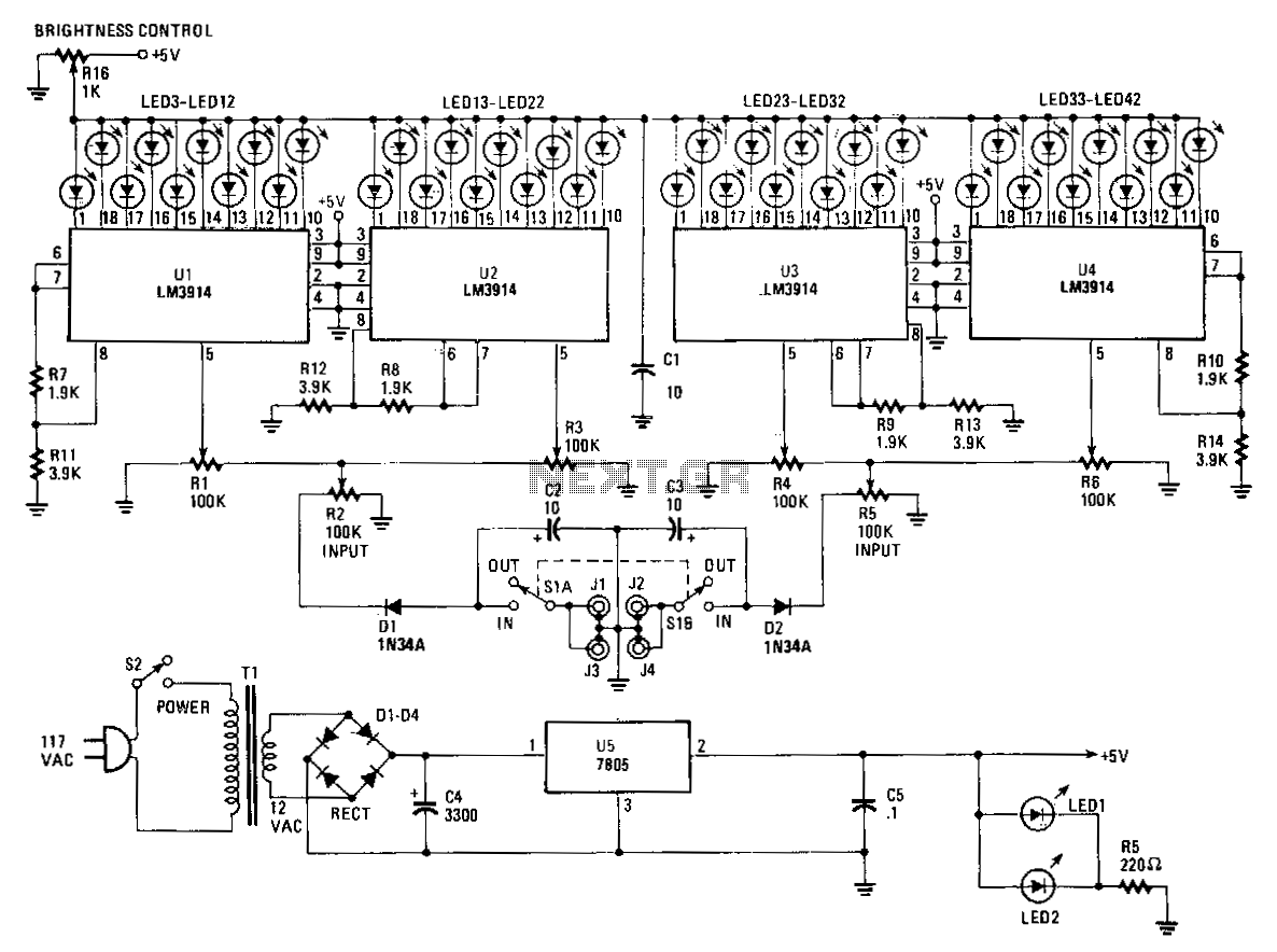
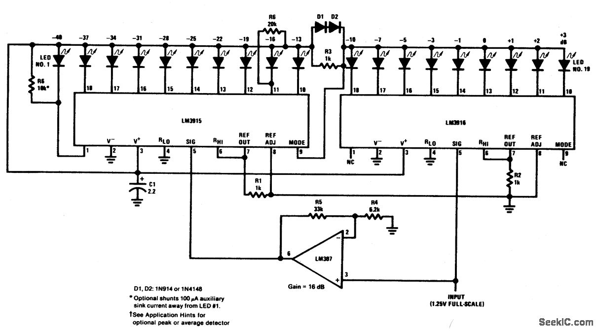
The Stereo Power Meter consists of two identical circuits and a power supply. Each circuit features two LM3914 display chips, which include 10 voltage comparators, a 10-step voltage divider, a reference voltage source, and a mode-select circuit that allows...
The process of calibrating the Smiths electronic tachometer revealed significant inaccuracies in its readings. A calibration technique was employed, similar to the one outlined in Tom Ballou's 1975 Tech Tip, using a dwell/tach meter at approximately 1200 RPM. This...
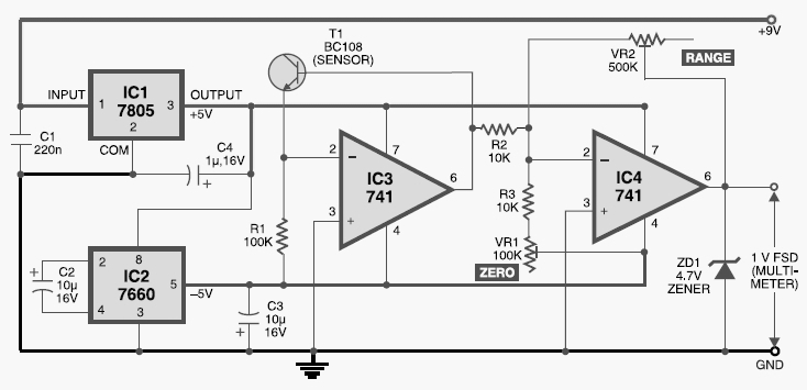
This digital thermometer circuit diagram uses a common 1N4148 diode as the temperature sensor. The temperature coefficient of the diode is -2 mV/°C. The digital thermometer circuit leverages the characteristics of the 1N4148 diode, which has a well-defined temperature coefficient....
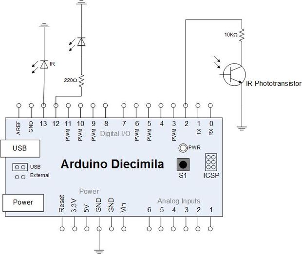
Yesterday, an attempt was made to read the infrared impulses from an electricity meter using a phototransistor. The phototransistor can detect infrared signals from various remote controls in the house but fails to detect the blinking signal from the...
This circuit can be utilized as a small beacon or marker light, as well as for toys or novelty items. R1 is a light-dependent resistor (LDR) that has a dark resistance of greater than or equal to 10 kΩ,...
Electronic potentiometer using a standard CMOS logic and analog multiplexers. Pot have low distortion (0.005% less at 1 V rms) and is it easy for beginners to understand. In the beginning, the art of Hi-Fi, in the absence of...