
Electronic potentiometer schematic


The electronic potentiometer circuit described utilizes CMOS logic and analog multiplexers to achieve low distortion and ease of use for beginners. The design is particularly relevant for audio applications, where high-quality volume control is essential. The circuit employs a resistive divider configured to provide approximately 4 dB steps between levels, which is critical for achieving smooth volume adjustments.
The use of two CD4051 analog multiplexers allows for the selection of 16 discrete levels, effectively replacing traditional mechanical switches with a more reliable electronic solution. The circuit's architecture ensures that the signal EN is routed through the multiplexers, enabling precise control over the output levels while maintaining low distortion characteristics.
An operational amplifier is incorporated as a voltage follower to maintain high input impedance, ensuring that the potentiometer's output does not load down the source signal. This is important for preserving signal integrity, especially when interfacing with other audio components. The load resistance for the potentiometer is specified to be at least 100 Ohms to ensure proper operation.
The control logic for the potentiometer is implemented using a CD4516 bidirectional binary counter. Each button press generates a clock pulse that increments or decrements the counter value, allowing for intuitive volume adjustments. The design includes an AND gate to manage the counting direction and prevent overflow, ensuring that the counter resets appropriately when reaching its limits.
For visual feedback, the circuit employs a U192 display driver, which translates the counter's output into a readable format, showing the current potentiometer setting. This is particularly useful for users to understand the volume level without ambiguity. Alternative display methods, such as using a 4511 or 4543 decoder, are discussed, though they are less suitable due to their limited digit display capabilities.
Overall, this electronic potentiometer design offers a robust solution for volume control in audio applications, leveraging modern CMOS technology to provide a user-friendly interface with reliable performance.Electronic potentiometer using a standard CMOS logic and analog multiplexers. Pot have low distortion (0.005% less at 1 V rms) and is it easy for beginers to Understanding. In the beginning the art Hi-Fi when in the absence of high-quality potentiometers for volume control using resistive divider, the various stages of the change lever mnohapolohovým switch. Figure 1 is the electronic equivalent of such a volume control. Instead I used a mechanical switch CMOS analog multiplexers. EN signal is collected by either a multiplexer, and so we have 16 steps. It might seem preferable to use instead of the two circuits 4051 a 16-channel multiplexer 4067, but that I was at the time of the potentiometer (around 1988) is unavailable. Even today, the two circuits 4051 are substantially cheaper than a 4067th The resistive divider is calculated so that the steps between levels are about 4 dB.
Member highlights C2R4 C1R3 height and a member of the bass at low volumes - implements the so-called physiological regulation. Follower operational amplifier provides high input impedance potentiometer divider of the excitation source with a defined impedance.
Load resistance of the potentiometer should be at least 100 Ohm. Originally, the potentiometer control microcontroller 8748th The IC is now obsolete and does not make sense for him to specify the program. More experienced designers can program a PIC or Atmel. For those who do not have to program a positive relationship is shown in Figure 2 control potentiometer circuit of ordinary logic IC.
Circuit 4516 is a bidirectional binary counter. When you press each button to generate a clock pulse when pressing "Down" in addition to the small time changes counting direction. AND gate controlled by signal transmission (CYO) zablohuje counting on reaching a maximum, respectively.
lows. Counter overflow and, therefore, begins to count again. AND gate can be replaced by two NAND gates as shown. Last open gate circuit 4093 can serve as an inverter for the signal A3. When power is generated at the input pulse PE. The outputs Q inputs override state P, which defines the counter after switching. Involvement of Figure 1 is needed for each channel once. The number of channels can be almost arbitrary. The control circuit is common to all channels. It remains to solve the indication "position potentiometer. I then used the circuit U192, which is used in television to indicate the preferences selected. This circuit jedenap?lmístném display shows the numbers 1 to 16 according to the status of the address inputs. Today you probably just got it in the bazaar. Less suitable alternative is to use a decoder to be 4511 or 4543rd These circuits, however, will show only the numbers 0 to 9, with a higher counter status display turns off.
🔗 External reference
Related Circuits
This circuit generates a ringing sound akin to that produced by modern telephones. It comprises three nearly identical oscillators arranged in a sequence, each responsible for generating a square wave signal. The frequency of each oscillator is determined by...
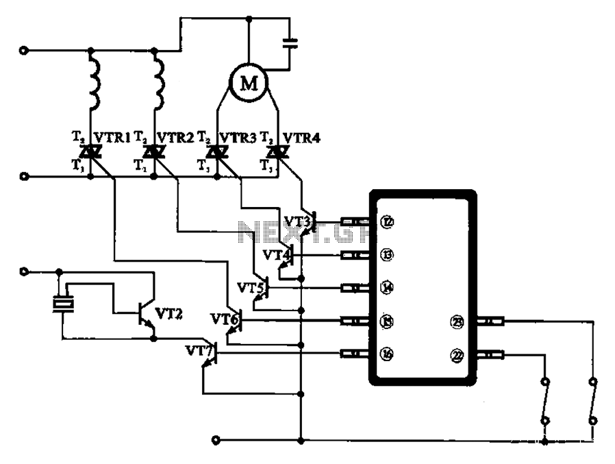
The schematic for the automatic washing machine motor driver outlines the motor drive circuit for the Narcissus XQB30-III-type washing machine. The control circuit comprises four Triacs, four drive transistors, and a control chip. This setup allows for the activation...
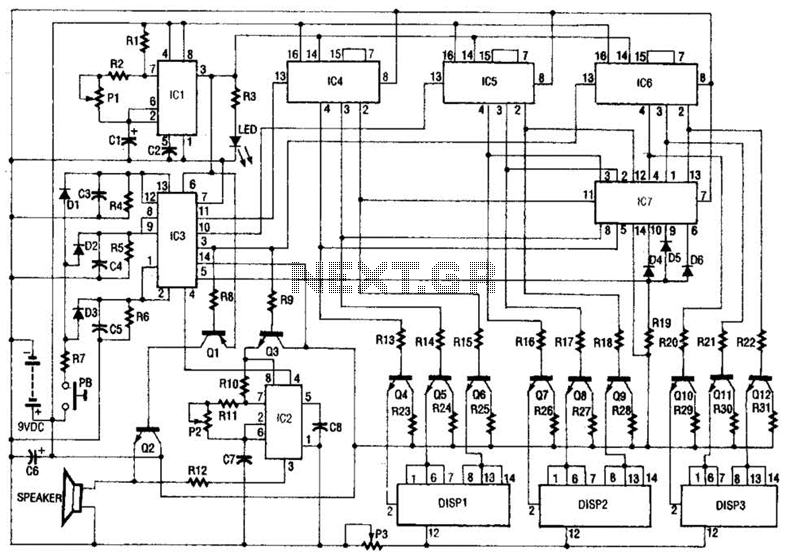
The slot machine's realistic action is provided by seven integrated circuits (ICs) and three displays. Two 555 CMOS timer ICs generate pulses. IC1 generates the clock pulses for the entire electronic slot machine. The pulses are coupled from the...
Laptops, commonly referred to as notebook computers, have gained significant popularity. Their portable design allows them to be easily transported in a bag, making them suitable for business trips and serving as convenient home entertainment centers due to their...
This document was created to address the numerous inquiries received about how to read a schematic. Learning to interpret a schematic diagram is akin to map reading; it requires understanding which wires connect to which components and identifying the...
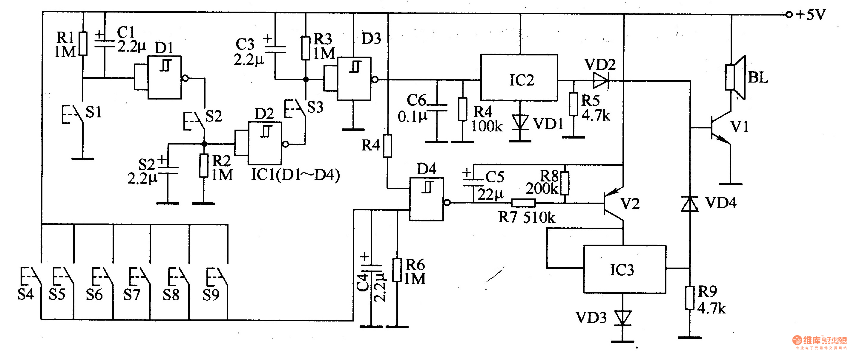
The password electronic doorbell circuit comprises a trigger circuit and a music generating circuit, as illustrated in Figure 3-119. The trigger circuit includes buttons S1-S9, four NAND gate Schmitt trigger integrated circuits (IC1), and external RC components. The music...