
EXTENDED RANGE VU METER

The circuit operates by using the light-dependent resistor (LDR) R1, which changes its resistance based on the ambient light levels. In low light conditions, the resistance of R1 increases, allowing more current to flow through the circuit. This change in current is used to charge capacitor C1, which is responsible for controlling the flash rate of the beacon.
When C1 charges to a certain voltage, it triggers a transistor or a similar switching component (not explicitly mentioned in the original description) to turn on an LED or another light source, creating a flashing effect. The flash rate can be adjusted by changing the capacitance of C1; a larger capacitor will result in a slower flash rate, while a smaller capacitor will increase the frequency of the flashes.
This circuit can be powered by a simple battery source, making it suitable for portable applications. Additionally, the use of an LDR allows the circuit to operate automatically based on surrounding light conditions, making it ideal for use in toys or novelty items that require a visual indicator or effect. The simplicity of the design allows for easy integration into various projects, providing an engaging and interactive experience.This circuit can be used as a small beacon or marker light, amd toys or novelty items. R1 is an LDR that has‰¥10 k © dark-resistance, or a CDS photocell. C1 determines the flash rate. 🔗 External reference
Related Circuits
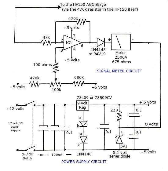
The operational amplifier (op-amp) used in the signal meter circuit is the TL061. The LF351 can also be used interchangeably, as it has the same pin layout. For those using a TL062 or similar models, the differing pin configurations...
This is the simplest VU meter that can be constructed. It is based on a single integrated circuit. A volume unit (VU) meter, or standard volume indicator, is a device used to display the level of any voltage signal...
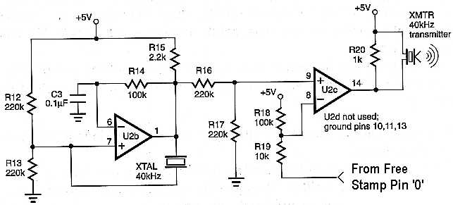
This project is ideal for use as a sensor in a robotic application. The circuit enables distance measurement from an object, with a measurement range of approximately 10 inches. An ultrasonic transmitter and receiver pair, tuned to 40 kHz,...
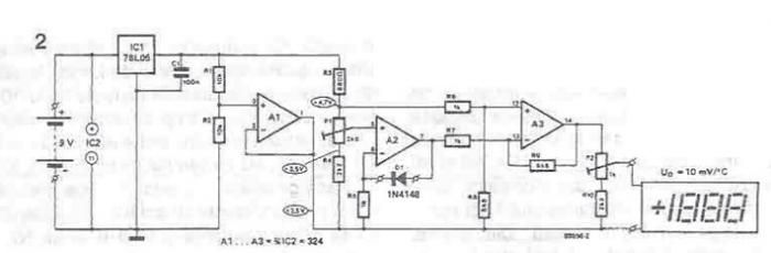
A simple thermometer can be constructed using operational amplifiers and a standard or protective diode, such as the 1N4148, as depicted in the electronic diagram below. A constant reference voltage is supplied to the non-inverting input of the operational...
You can build an automatic gain control AGC for the superhet receiver with only a few additional components. The first AGC circuit is more universal. It is suitable for audio amplifiers with dual op amps like TL072, TL082, NE5532...
In this project, you will make a simple 3-stage low-power broadcast-type circuit, using a crystal oscillator integrated circuit and a collector modulated AM oscillator with amplifier. You can connect the circuit to an electret microphone or amplified dynamic microphone....