
Electronic thermostat circuit

The thermostat circuit is designed to control the temperature of a system by switching between different power levels. The circuit includes a DIP switch (SA) that allows the user to select between three operational modes: off, low power (Lo), and high power (Peru HL).
In the low power mode, when the switch is set to Lo, the circuit allows 220V AC to flow through diodes VD4 and VD56. These diodes serve as rectifiers, converting the AC voltage to a pulsating DC voltage through half-wave rectification. This process effectively reduces the voltage supplied to the load (RL), which is crucial for applications requiring lower heat output. The reduction in voltage results in a significant decrease in the power dissipated by the load, thereby lowering its temperature.
The circuit's design ensures that in the high power mode (Peru HL), the load receives the full 220V AC, allowing for maximum heating capability. The off position completely disconnects the load from the power supply, ensuring that no current flows and the load remains inactive.
This thermostat circuit is commonly used in heating applications where precise temperature control is necessary. By utilizing the DIP switch to select the desired power level, users can effectively manage the thermal output of the system, ensuring optimal performance and energy efficiency.Thermostat electric circuit as shown in FIG. It points to off (off), Lo (low power), Peru HL (high power) third gear. When DIP switch SA to Lo gear, 220V electricity through the diode VD4, VD56 added to the load RL ends; half-wave rectified by a diode so that RL was significantly lower than when the operating voltage 220v straight, so RL temperature drops.
Related Circuits
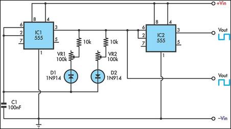
This timer utilizes two 555 integrated circuits (ICs) to adjust the desired output. The variable resistors VR1 and VR2 serve as potentiometers to modify the cycle speed. The circuit can be powered with a 9 to 12-volt power supply,...
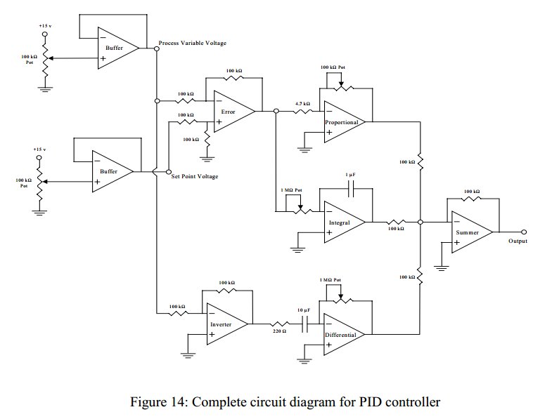
Convert a feedforward operational amplifier PID loop to C code. Assistance is needed for this conversion, as the process is unfamiliar. Input values can be obtained through an ADC, such as voltage or current, but coding a feedforward PID...
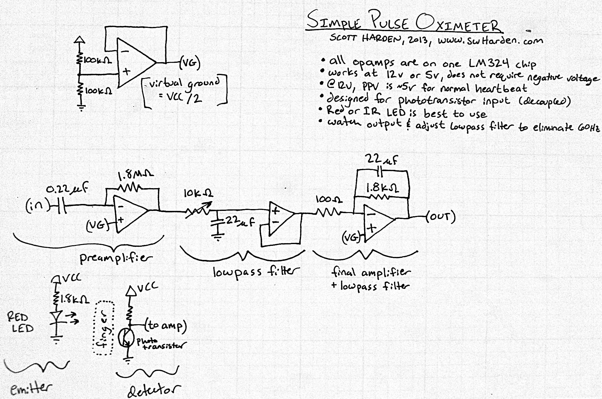
The input capacitor for the phototransistor at the bottom is responsible for feeding the operational amplifier (op-amp). However, the output from the phototransistor consistently remains between ground (GND) and the supply voltage (Vcc). The necessity for an input capacitor...
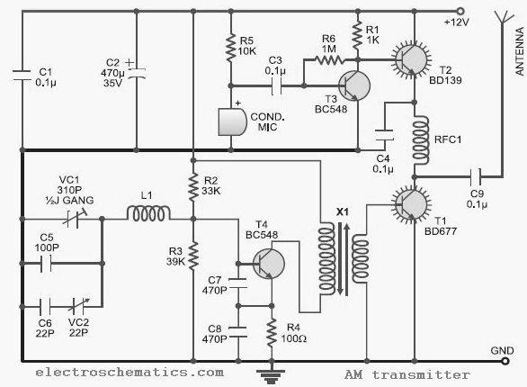
This low-cost AM transmitter is tunable from 10 to 15 MHz with the assistance of a ½J gang condenser VC1, which sets the carrier frequency of the amplitude modulation transmitter in conjunction with inductor L1. Frequency trimming can be...
This is a digital dice circuit that uses the PIC16C84. The digital dice circuit utilizing the PIC16C84 microcontroller is designed to simulate the random rolling of a standard six-sided die. The circuit operates by generating a random number between 1...
Dual power automatic recovery means one power supply and one standby power supply. When the main power supply is turned off, the standby power supply is automatically activated. Once the main power supply is restored, the system automatically exits...