
Functional subwoofer amplifier circuit
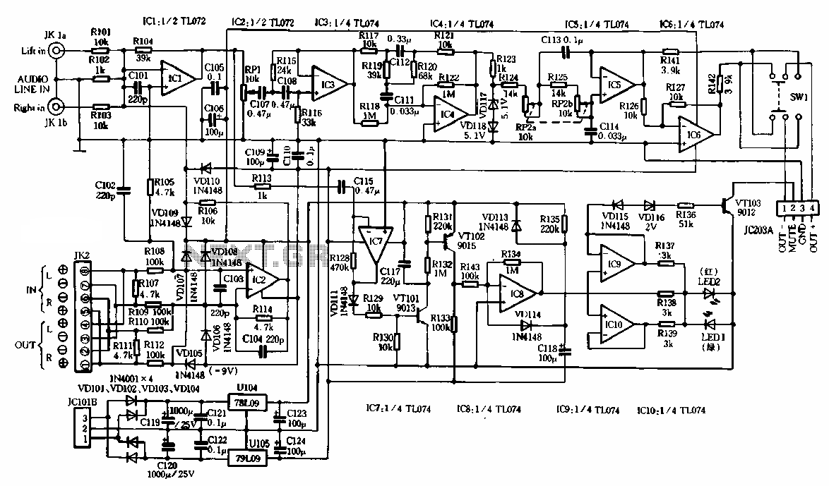
Typically, high-power amplifiers include speaker protection circuits, which can be problematic if they rely on relay contacts that may introduce signal distortion. In active speakers, the relay can produce audible clicks during strong low-frequency signals. Therefore, for high-power subwoofers, it is advisable to design the amplifier with reliable protection features using discrete components instead of relying solely on relay systems. Observations from YAMAHA and SONY active subwoofers indicate that they often limit output power to around 50W, rarely functioning in bass-heavy scenarios. Utilizing the LM3886 as an active subwoofer amplifier allows for leveraging its excellent protection features, including overheating, overcurrent, overvoltage, and over-power safeguards, thereby reducing the need for additional speaker protection circuitry.
For practical implementation, two LM3886 power ICs should be mounted on an aluminum heatsink measuring 200mm x 50mm x 30mm, ensuring proper airflow across the heatsink. To achieve optimal thermal management, the pre-amplifier and power amplifier circuits should be designed on separate printed circuit boards (PCBs). The amplifier board should be positioned above the heatsink, facilitating airflow from the bottom of the enclosure. This configuration is essential for powering a 12-inch subwoofer at a rated output power of 100W sine wave, while preventing excessive power from being applied to the speakers. The pre-amplifier circuit incorporates resistors R123 and diodes VD117 and VD118 to achieve this goal.Shown respectively for the subwoofer amplifier stage pre-amplifier circuit and the signal processing circuit. Here, in particular, the choice of the two American NS company recently produced LM3886 power lC way to promote access to BTL speaker impedance standard work 8fl in distortion requirements of less than 0.2%, the continuous sine wave output of 100W rated power. It should be noted clearly, I-M3886 is improved Ic NS company in I-M3886 basis, although each said its product introduction IJM3886 maximum possible sine wave output 68W rated power, but because of its internal design has a perfect over-power protection , in excess of 50w output power supply conditions, but it will be in low-amplitude signal its power consumption limit value for protection movement for leaving the ferry cut output signal distortion, we should just make it work at rated output power less than 50w the state.
As we all know, a little better all the high power amplifier plus a speaker protection circuit, and cut off the speaker can only switch the operating current is no pressure drop relay contacts. However, the active speaker is mounted inside the relay, when the speaker issued a strong low-frequency ' sound when the ratio, the contact of the relay will generate mechanical sound interrupt jitter phenomenon q So, for larger power bass guns powered speakers, not on the circuit may affect the use of speaker protection relay system to work.
Thus, we should also seek to have the power amplifier is perfect and reliable security features using discrete components to create these projections sound fine fatal flaw is also here, and we YAMAHA SONY company's three active subwoofer speakers been found, we found that they actually limit the output power of about 50w, and rarely work in the bass heavy situations. Using LM3886 amplifier lC to serve as an active subwoofer amplifier, just to take advantage of its perfect overheating, over current, over voltage, over power protection function to relieve other speaker protection circuitry requires additional design 6 Proof of actual use, two LM3886 power should put lC with ZOOmm 50mm 30mm size aluminum radiator, and should maintain a flow of air blown in the radiator top.
To this end, the pre-and post-stage power amplifier circuit design into two separate printed circuit board, so that the amplifier board single security alone at the top after the radiator, and then install it inside the box inside the tube can be inverted air blowing out of position white has enough to push 12 t caliber subwoofer work rated output power of 100W sine wave, we need to avoid excessive output of the power applied to the speakers. T do this in the pre-circuit, designed by the resistor R123 and two VD117.VD118
Related Circuits
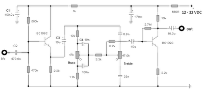
The first BC109C transistor functions as a buffer, delivering a high input impedance of approximately 250k and exhibiting a voltage gain marginally below unity. Given that the Baxendall tone control circuit operates passively, it attenuates all audio frequencies. The...
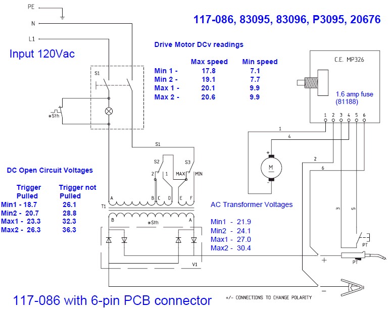
The wire speed DC motor consistently receives approximately 20 volts, irrespective of the switch position on the nozzle handle. The switch has been tested with an ohmmeter and functions properly. Even after disconnecting the switch from the circuit board,...
This amp delivers a lot of power and uses 1 IC and two power transistors. The circuit consists of an amplifier IC (a TDA 2030A) and a power stage consists of two transistors. The amplifier can be powered with...
The motor control circuit depicted in the image utilizes the LM339 comparator among other components. When the input control signal is high (PWL), comparators A and A3 activate the power amplifier circuit, which consists of A4, VT5, and VT6,...
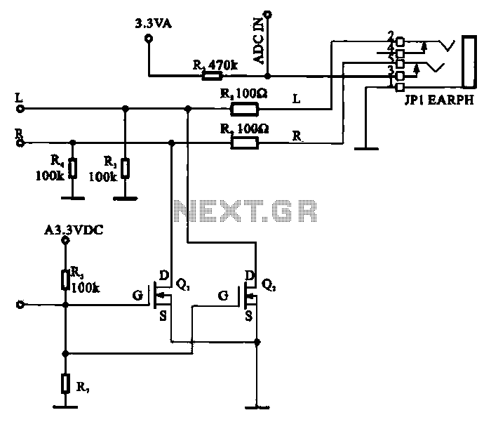
A field-effect transistor (FET) is utilized in a headphone circuit designed to function as a silencer tube. The circuit integrates L from the digital signal processing unit and R from the audio signal into the headphone jack's mute control...
This is a compact collection of amplifiers configured in a bridge connection. The output power is low, making them suitable for general applications. They can be utilized with small active loudspeakers, car stereos, and similar devices. The only limitation...
Warning: include(partials/cookie-banner.php): Failed to open stream: Permission denied in /var/www/html/nextgr/view-circuit.php on line 713
Warning: include(): Failed opening 'partials/cookie-banner.php' for inclusion (include_path='.:/usr/share/php') in /var/www/html/nextgr/view-circuit.php on line 713