
Improved Arduino TV-B-Gone

The TV-B-Gone circuit operates by utilizing an infrared LED to transmit a series of codes corresponding to various television brands. Each code is designed to power off the television when received. The circuit is powered by an Arduino microcontroller, which is programmed to send these infrared signals in a specific sequence. The compact design allows for easy handling and portability, making it a convenient tool for quickly turning off televisions in public spaces.
The schematic for the Arduino TV-B-Gone includes several key components: the Arduino board, an infrared LED, a trigger switch, and various resistors and capacitors to ensure stable operation. The infrared LED is connected to Pin 3, which is responsible for transmitting the infrared signals. The trigger switch, located on Pin 2, initiates the transmission sequence when pressed. The grounding of Pin 5 is crucial for enabling the European codes, allowing the device to function across different regions.
In terms of assembly, the circuit requires careful attention to the connections outlined in the schematic. Proper soldering techniques should be employed to ensure reliable connections, particularly for the infrared LED and the trigger switch. Once assembled, the code must be uploaded to the Arduino, which will dictate the operation of the TV-B-Gone. This project exemplifies the integration of software and hardware, demonstrating how modifications to the code can enhance functionality and user experience.
For those interested in further customization, the code can be modified to include additional television brands or to adjust the timing of the code transmission. This flexibility allows users to tailor the device to their specific needs, making the TV-B-Gone not only a practical tool but also a platform for learning and experimentation in electronics.The TV-B-Gone is a tiny infrared remote that can turn off almost any TV. A while ago, I ported the TV-B-Gone software to the Arduino; for details on the port and how it works see my previous post on the Arduino TV-B-Gone. Mitch Altman, the inventor of the TV-B-Gone, made some improvements to the code for a weekly TV-B-Gone constructing workshop i
n San Francisco at Noisebridge. If you`re in the San Francisco area and are interested in the TV-B-Gone, you might want to check it out. The main bug fix in the new version is the European codes will now work (if you ground pin 5). (The problem was a bunch of #ifdefs to fit the codes into the ATtiny`s limited memory; taking out the #ifdefs fixed the problems.
) Pressing the trigger button during transmission will now restart the codes. The delay between codes was increased, which should make transmission more reliable. The Arduino`s processor will now sleep when not transmitting (thanks to ka1kjz ). (Unfortunately, the rest of the Arduino components are still draining power, so sleep mode will be more useful with stripped-down Arduino variants. ) Important: the pins have been changed around in the new version (to avoid conflicts with the serial port).
Pin 2 is now the trigger switch, Pin 3 is the IR output, and Pin 5 is grounded if you want European codes. If you built an Arduino TV-B-Gone before and want to use the new code, make sure you connect to the right pins.
To build the Arduino TV-B-Gone, follow the above schematic and download the sketch. My previous post on the Arduino TV-B-Gone has more information on wiring it up, if you need it. 🔗 External reference
Related Circuits
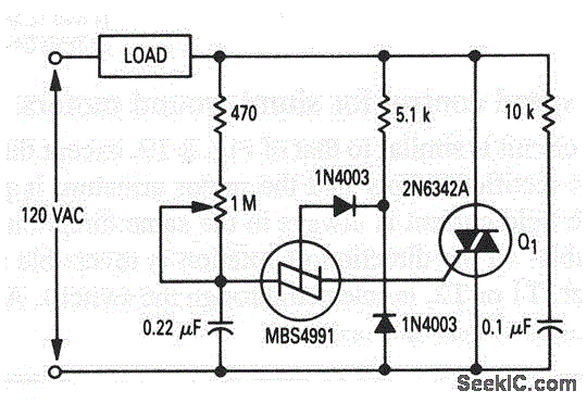
This circuit is an enhanced version of the circuit depicted in Figure 8-21. The hysteresis effect has been mitigated through the incorporation of two diodes and a 5.1 kΩ resistor. An RC network is connected across the TRIAC, functioning...
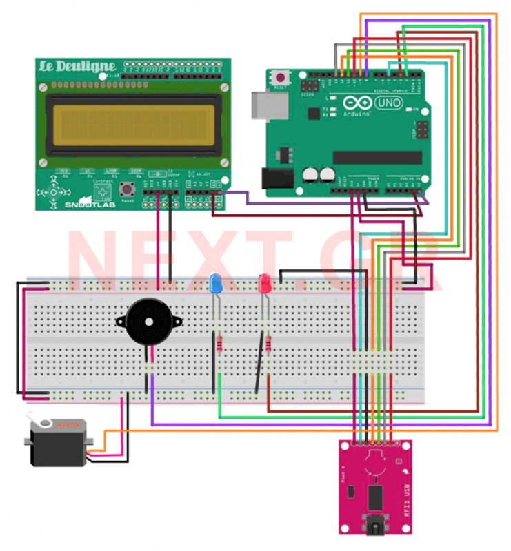
This project aims to develop a security system suitable for business environments or for simple home use. The system utilizes an Arduino Uno microcontroller in conjunction with RFID (Radio Frequency Identification) technology, enabling wireless user identification. Only registered users...
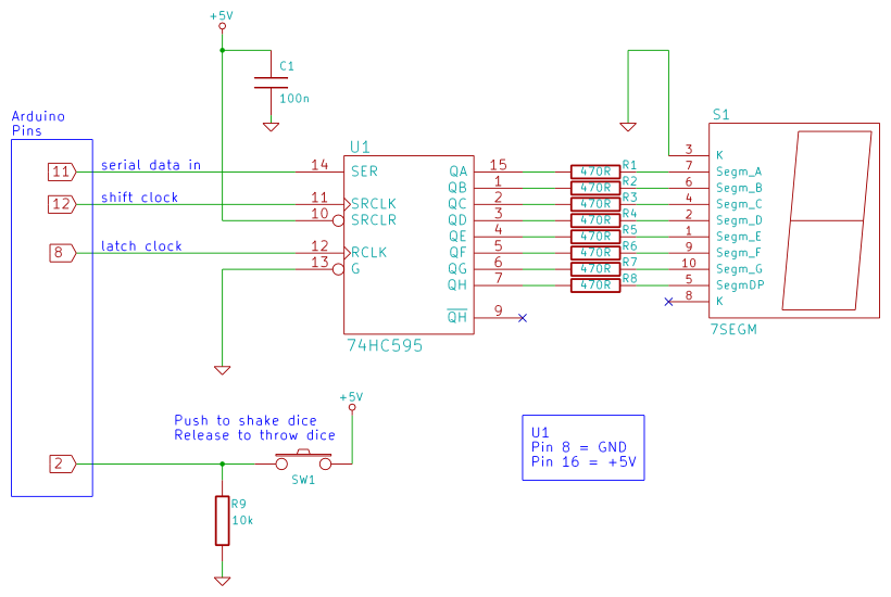
Arduino 7-segment display dice circuit and tutorial with Arduino sketch. Build a dice that is shaken by holding a button in and thrown by releasing the button. The shake, throw, and number thrown are animated and displayed on a...
This sketch transmits an ASCII 'A' (byte value 65) upon startup and continues to do so until it receives a serial response from the computer. After receiving a response, it sends three sensor values as individual bytes and waits...
Sometimes, it is necessary for a program to halt execution while a specific condition remains true. This can be accomplished using a while loop. The following example illustrates the application of a while loop to calibrate the value of...
The circuit functions adequately, although it is not ideal in terms of quality. However, there is a minor issue when interfacing the output with an Arduino. The output swings below ground, meaning it is biased at 0V, while the...