
Watch Tick Timer Circuit
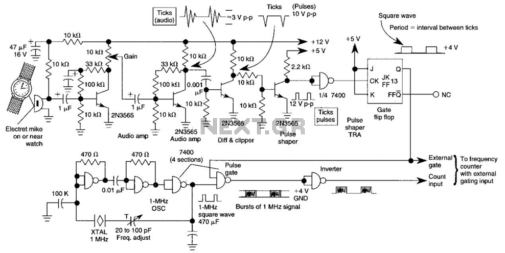
The described circuit effectively transforms time intervals into measurable electrical signals, allowing precise analysis of timing events. The core component, a 1-MHz TTL crystal oscillator (XTAL OSC), provides a stable and accurate time base. The oscillator generates a continuous square wave signal, which serves as the reference for timing measurements.
The circuit begins with the input of watch ticks, which are analog signals representing time markers. These analog signals are processed through a clipping and shaping stage, where they are converted into a clean square wave signal. This transformation is crucial as it ensures that the timing intervals can be accurately represented in a digital format suitable for counting.
Once the square wave is generated, it is used to gate the clock signal from the 1-MHz oscillator. The gating process allows the external counter to count the number of clock pulses that occur during the specific interval defined by the incoming square wave. This counting mechanism is vital for determining the duration of the measured interval with high precision.
The resolution of the measurement is determined by the frequency of the clock signal. In this case, the 1-MHz clock allows for a resolution of 1 microsecond, which is equivalent to one count in the least significant bit (LSB) of the counting process. This high level of accuracy makes the circuit suitable for applications requiring precise timing measurements, such as evaluating shutter speeds in photography.
In summary, the circuit is a robust solution for measuring time intervals, leveraging a combination of analog signal processing and digital counting techniques to deliver accurate and reliable results. This circuit adapts a frequency counter to measure intervals. It was originally used as a shutter speed checker for a photo application. The watch ticks are clipped and shaped and formed into a square wave. This square wave is used to gate an accurately known clock (1-MHz TTL XTAL OSC) and an external counter is used to directly count the clock pulses during the interval to be measured. A 1-MHz clock can be used to measure to a resolution of 1 Accuracy = time base 1 1 count LSB. 🔗 External reference
Related Circuits
A highly beneficial project involving a crystal tester circuit, also known as an xtal tester circuit, constructed with only a few components. The circuit forms an oscillator that will only oscillate if the crystal under test is functioning properly....
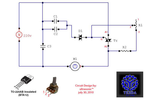
This circuit functions as a motor controller, allowing for easy control and variation of the RPM and phase of an AC motor. The power source is directly 220VAC, and it can handle a load of approximately 1 horsepower AC...
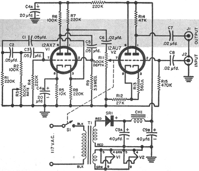
RF Cafe visitor Jim L. requested that this "Build Your Own Vibrato" article from the December 1957 edition of Popular Electronics be posted. The tagline states, "Make like Elvis with an electronic throbbing guitar." Vibrato, for those unfamiliar with...
This document presents the circuit diagram of an IC-controlled emergency light with a charger, which functions as a 12V to 220V AC inverter circuit. The primary features of this circuit include automatic activation of the light during mains failure...
This radio modem is widely used for amateur radio packet applications. It is powered by the data and control lines, eliminating the need for additional power sources. The radio modem operates by facilitating packet data communication over amateur radio frequencies....
The Olimex P-40 development board will be utilized, though the circuit can also be constructed on a breadboard due to its simplicity. The schematic for the initial implementation of servo control is provided below. Servos, like any motors, can...