
IMPROVED TV COLOR WHEEL CONVERTER
Another advantage of Col-R-Tel is its delay line, which is installed before the final luminance amplifier. Although this installation takes additional time, the 1.3 µs delay aligns the color and monochrome images, resulting in a clear and vibrant picture. The original Col-R-Tel circuit operates without a delay line; however, the slight misalignment can be noticeable to discerning viewers. Col-R-Tel has developed its own delay line, which processes chroma less than Colordaptor does. Consequently, the Col-R-Tel delay only requires 800 nanoseconds. The shorter delay line requirement demonstrates the success of the Indiana engineers; tests conducted by Cliff Benham have shown that Col-R-Tel has a flatter and wider color bandwidth compared to Colordaptor. The delay line schematic illustrates this component. The Col-R-Tel delay line reduces contrast, and during monochrome reception, it can be deactivated by switching it out of the circuit. A 15 kΩ resistor and a 0.002 µF capacitor load the delay line to reduce reflections (ghosting). Some receivers may require slightly different loading values, which should be determined experimentally. For a period in the late 1950s, Color Converter, Inc. marketed its 800 nanosecond delay line for Col-R-Tel. With the delay line and improved video pickup, Col-R-Tel's picture quality is exceptional.
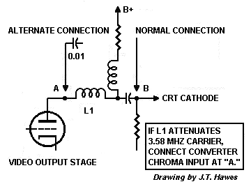
For those looking to enhance their Col-R-Tel to meet the high standards set by Columbia City, Indiana's leading engineers, Toko offers delay lines that could be compatible with solid-state TVs. Cliff Benham has noted the part number H318LNKN2601WAE, which corresponds to Toko's 400 ns, 1.2 kΩ delay line, priced at approximately $3.00. It is possible to cascade two of these lines to achieve an 800 ns delay. Dallas Semiconductor provides semiconductor delay lines in dual inline packages (DIP), with 200 ns lines that can be easily cascaded. Each integrated circuit includes three 200 ns delays and requires a 50-ohm source, which may be low for tube applications. The Dallas part is available at Digikey, and the datasheet can be found under Dallas delay line. Additionally, it is recommended to add a preamplifier, as one of Col-R-Tel's limitations is the absence of a true chroma bandpass amplifier.d 101-2 depend on the TV to supply a wide bandwidth video signal. Most black-and-white TVs from 1954 on contain narrowband IF strips or low-pass filters. A wide passband is a disadvantage, because it picks up the chroma signal. In a black-and-white TV, the chroma signal interferes with the monochrome signal. Today, comb filters take care of this p roblem. Back in 1955, comb filters are an engineering fantasy. The narrowband IF or low-pass filter has to do. Narrow & Wide IFs. Unfortunately, the resulting passband seems to attenuate chroma and burst signals that Col-R-Tel depends on. Col-R-Tel picks up its signal at the CRT cathode. Yet the signal that arrives there is often too weak to be useful. For color adapters, it`s not a fair world. Engineering ingenuity to the rescue. Col-R-Tel engineers discover that the problem actually isn`t the IF strip or low-pass filters. The real problem An inductive peaker in the final video amplifier`s plate circuit. See the schematic. After the peaker, some TVs provide an excellent chroma signal. This is the traditional Col-R-Tel connection, where the last video plate meets the CRT cathode. On other TVs, the signal there contains attenuated highs. With these TVs, the trick is to move the yellow Col-R-Tel input wire. The new connection is through a 0. 01 uF capacitor. Connect the capacitor to the plate side of the inducive peaker. The capacitor isolates Col-R-Tel from high voltage DC at the plate. Color Converter, Inc. also adds an LC series filter between the TV and the Col-R-Tel coupling capacitor. This filter reduces video smearing. Col-R-Tel`s delay line. Another Colordaptor advantage is its delay line. Installing the delay line before the final luminance amplifier takes a little extra time. But the 1. 3 uS delay lines up the color and monochrome pictures. The result is a nice, clear, snappy image. The original Col-R-Tel circuit operates without a delay line. Col-R-Tel`s misalignment is slight, but persnickety viewers can see it. Shorter delay. Col-R-Tel has to come up with its own delay line. And Col-R-Tel engineers do exactly that. Col-R-Tel doesn`t process the chroma as much as Colordaptor does. Apparently for this reason, the Col-R-Tel delay only needs to be 800 nanoseconds. Incidentally, the shorter delay line requirement points out another triumph for the Indiana engineers: As Cliff Benham`s tests prove, Col-R-Tel has a flatter, wider color bandwidth than Colordaptor does.
See the delay line schematic. The Col-R-Tel delay line reduces contrast. During monochrome reception, you can deactivate the line by switching it out of the circuit. A 15 K resistor and 0. 002 uF capacitor load the delay line. Loading reduces reflections (ghosts). Some receivers require slightly different loading values. Determine these values experimentally. For awhile in the late 1950`s, Color Converter Inc. sells its 800 nanosecond delay line for Col-R-Tel. With the delay line and new video pickup, Col-R-Tel`s picture is a sight to behold. Commercial delay line sources. For those who`d like to upgrade their Col-R-Tel to the world-class standards of Columbia City, Indiana`s foremost engineers. Toko. Cliff Benham notes that TOKO makes delay lines that might work with a solid-state TV. Cliff is interested in the part number H318LNKN2601WAE. This part is the TOKO`s 400 nS, 1. 2K ohm delay line. Cliff says that the price is only some $3. 00. He mentions that a builder could cascade two lines to achieve an 800 nS delay. Dallas Semiconductor offers semiconductor delay lines in dual inline packages (DIP). The 200 nS lines should be easy to cascade. Each IC includes three 200 nS delays. These lines require a 50-ohm source. (Unfortunately, this impedance is quite low for a tube application. ) Digikey stocks the Dallas part. For the datasheet, see Dallas delay line. Add a preamplifier. One of Col-R-Tel`s weaknesses is that it has no true chroma bandpass amplifier 🔗 External reference
Related Circuits

Frequency converter schematic, frequency to voltage converter schematic, frequency to voltage converter using TR, voltage to frequency converter application. A frequency converter is an essential electronic circuit that transforms frequency signals into corresponding voltage levels or vice versa. The frequency...
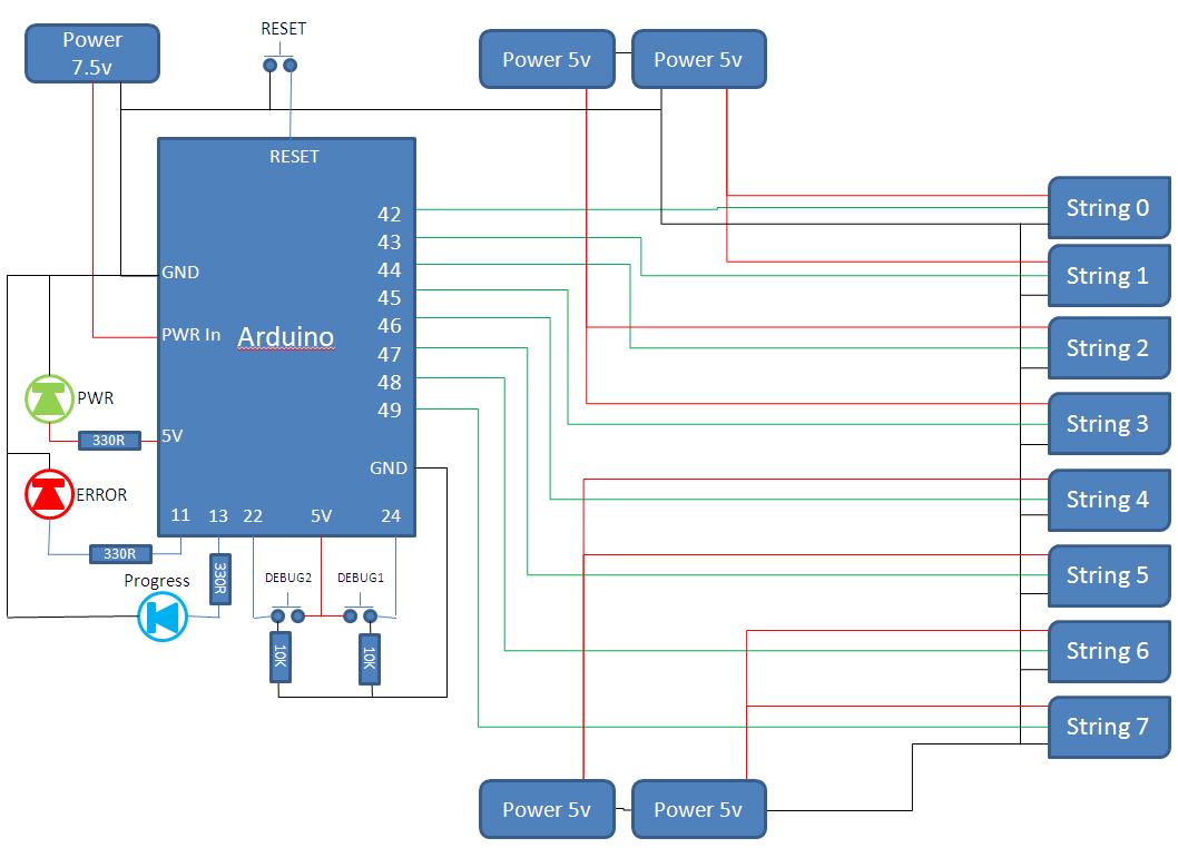
This project develops a Christmas lights controller for GE Color Effects lights, enabling programmed control of up to eight sets of lights. It includes a function-specific language for programming light patterns and an emulation environment for testing programs before...
In many situations, there is a need for a 220VAC voltage supply in areas where it is not readily available to power various small appliances. Figure 1 illustrates a voltage converter circuit that converts 12VDC to 220VAC, with an...
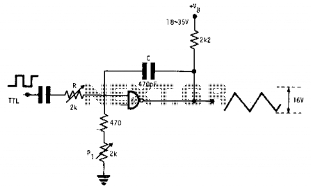
This fixed-frequency triangular waveform generator, driven by a TTL square wave, produces triangular waveforms with a peak-to-peak voltage of typically 16 V at frequencies reaching several MHz. The design utilizes a single AND open collector gate or an open...
This circuit accepts positive, negative, or differential control voltages. When the control voltage is zero, the output frequency is also zero. The described circuit functions as a versatile control voltage interface, capable of processing a range of input signals, including...
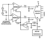
The Common Mode Rejection Ratio (CMRR) facilitates the rejection of high-frequency common-mode voltages, leading to the attenuation of elevated ambient noise levels from utility lines, industrial machinery, and other sources of radiation. The circuit diagram presented illustrates the advantages...