
Improving the MICOR Receiver for 435-450 MHz
The modification of the UHF MICOR "M" range receiver board involves several key steps and component replacements to enhance its performance in the desired frequency range. The core of this procedure lies in the adjustment of the receiver's tuning capabilities, which is critical for maintaining signal integrity and sensitivity in the lower frequency spectrum.
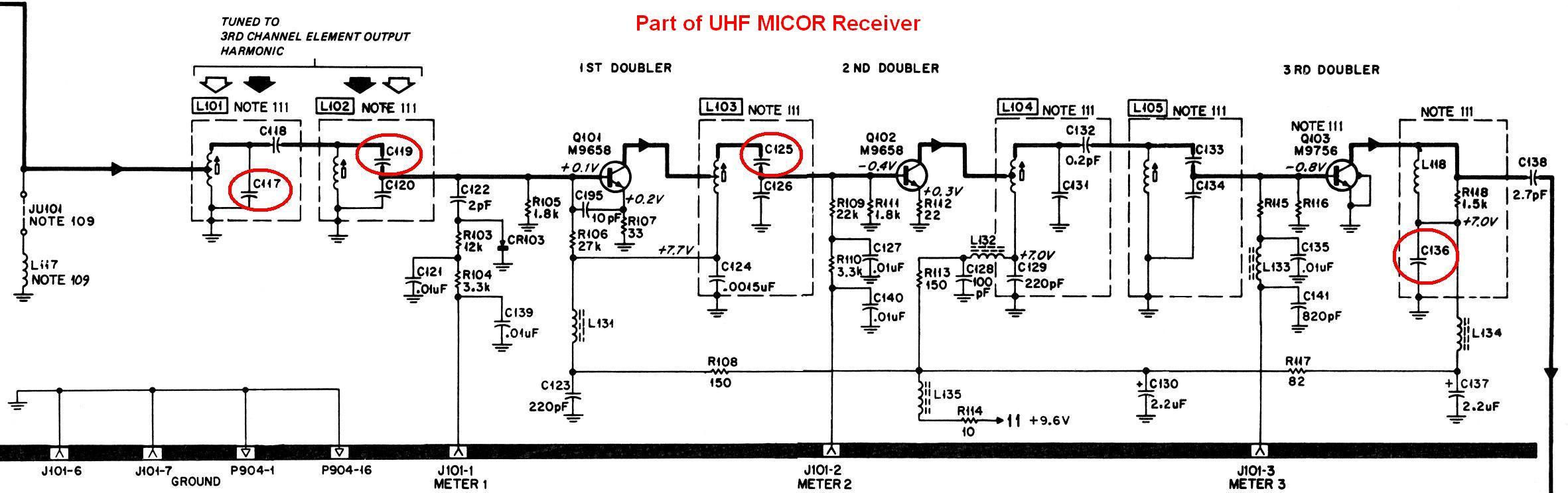
First, it is essential to identify and access the components that require replacement. The capacitors C117, C119, and C125 are crucial for adjusting the tuning characteristics of the receiver. Replacing these capacitors with values specified for the "L" range boards will allow the receiver to effectively operate within the 435-450 MHz range. It is recommended to consult the provided table for the exact values needed for these replacements.
In addition to the capacitors, attention must be given to the coils L111 through L116. These coils play a significant role in the oscillator's performance and overall tuning range. Since the original parts may no longer be available, it is advisable to source equivalent components that can provide similar inductance and quality factors. The proper selection of these components is critical for ensuring that the receiver maintains its performance across the modified frequency range.
Furthermore, the capacitor C136 should also be considered, as its modification can yield slight improvements in sensitivity. Although the enhancement may be marginal, it demonstrates the importance of precision in component selection and adjustment. Utilizing advanced testing equipment may be necessary to quantify these improvements effectively.
Overall, the successful modification of the UHF MICOR "M" range receiver board requires careful attention to the specified components and their values, as well as a thorough understanding of the receiver's operational characteristics. Following these guidelines will facilitate an effective transition to the desired frequency range while maintaining the integrity and performance of the receiver.This is a detailed explanation of a procedure you can use to modify a UHF MICOR "M" range (450-470 MHz) receiver board so it operates adequately in the 435-450 MHz range. This is an enhancement to Kevin`s text-only article. These receivers are commonly found in a Spectra TAC chassis as well as base stations, mobiles, and satellite receivers.
They will meet specs down to about 445 MHz; then things start deteriorating. While the receiver will, in general, perform adequately down to nearly 440 MHz, the crystal oscillator multiplier stages seem to run out of tuning range around 445 MHz. This condition can be fixed by replacing some components with values appropriate for the "L" range boards.
You can do this one of two ways: Kevin`s original article only mentioned replacing C117, C119, and C125. An e-mail received by Repeater-Builder from an ex-Motorola Service Shop technician contained a parts list for an export model MICOR that covered 420-450 MHz.
This conversion included replacing several coils (L111 through L116) with parts that are no longer available. Information about C136 came from this source. Sensitivity with C136 padded is marginally better but you`d need sophisticated instruments to see it.
Here`s a table showing the capacitor reference number, the original value for the "M" range (450-470 MHz), the value you`d need to replace it with (the "L" range), or the value you`d need to add across the existing component to get it to the "L" range. All values are in picoFarads. 🔗 External reference
Related Circuits
Many audio systems consist of separate units, and due to economic reasons, only the amplifier is equipped with a remote control receiver module. Control signals are then transmitted to other units using patch cables. For instance, the tuner and...
Wireless headphone transmitter and receiver systems are now widely available in the market, offering a variety of pricing options along with reliable technical specifications for various applications. These include wireless headphones for televisions, computers, and earbuds. A wireless headphone...
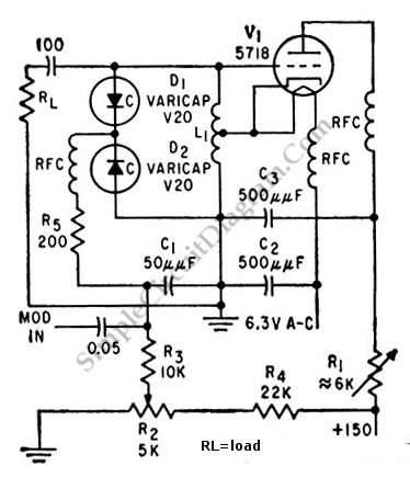
This is a 100 MHz varicap oscillator circuit. It can provide modulation signals of less than 28 V and a frequency deviation of 28 MHz peak-to-peak. The 100 MHz varicap oscillator circuit utilizes a varactor diode, which is a semiconductor...
This circuit enables the generation of audio musical notes that can be heard from a distance of up to 10 meters. It consists of two main components: an infrared (IR) music transmitter and an IR music receiver. The IR...
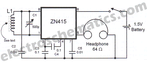
There are instances when a radio station can be found, and other times when no stations are detectable. The primary issue while tuning appears to be that any movement of the hands or body, such as releasing the tuning...
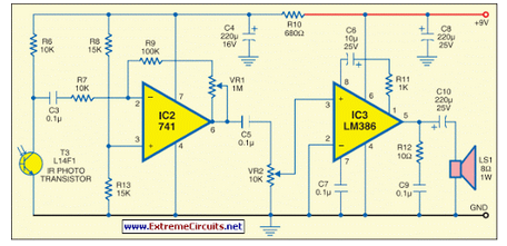
This circuit generates audio musical notes that can be heard from a distance of up to 10 meters. The circuit is divided into two parts: an infrared (IR) music transmitter and a receiver. The circuit operates on the principle of...