
100MHz Varicap Oscillator

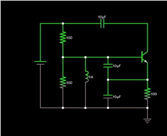
The 100 MHz varicap oscillator circuit utilizes a varactor diode, which is a semiconductor device that exhibits a variable capacitance as a function of the applied reverse voltage. This property is leveraged in the oscillator design to achieve frequency modulation. The circuit typically comprises an LC tank circuit, where the inductor and the varicap diode form a resonant circuit capable of oscillating at the desired frequency.
In this configuration, the varicap diode is reverse-biased, allowing its capacitance to change with the voltage applied across it. By modulating this voltage, the frequency of the oscillation can be varied, achieving the desired frequency deviation of 28 MHz peak-to-peak. The output signal can be further amplified using an RF amplifier stage to ensure that the modulation signals are adequate for transmission or further processing.
The power supply for the circuit is designed to provide a stable voltage of less than 28 V to ensure the proper operation of the varicap diode and other active components. Careful selection of the inductor and the varicap diode's characteristics is crucial in achieving the desired performance, including stability and linearity of the modulation.
Overall, the 100 MHz varicap oscillator circuit is a versatile solution for generating high-frequency modulation signals, suitable for various applications in communication systems and signal processing. Proper layout and shielding techniques should be employed in the PCB design to minimize noise and ensure signal integrity.This is a 100MHz Varicap Oscillator circuit. This circuit can provide modulation signals less than 28V and frequency deviation of 28 MHz peak-to-peak. This.. 🔗 External reference
Related Circuits
A PLL (Phase-Locked Loop) oscillator is utilized to achieve a very stable frequency with minimal distortion in the sine wave output. Its stability is comparable to that of crystal-based oscillators, while the distortion level of the sine wave output...
A voltage-controlled oscillator (VCO) is an electronic signal generator that produces a signal with a variable frequency, which is dependent on an input voltage level. A voltage-controlled oscillator is a fundamental component in various electronic applications, including phase-locked loops (PLLs),...
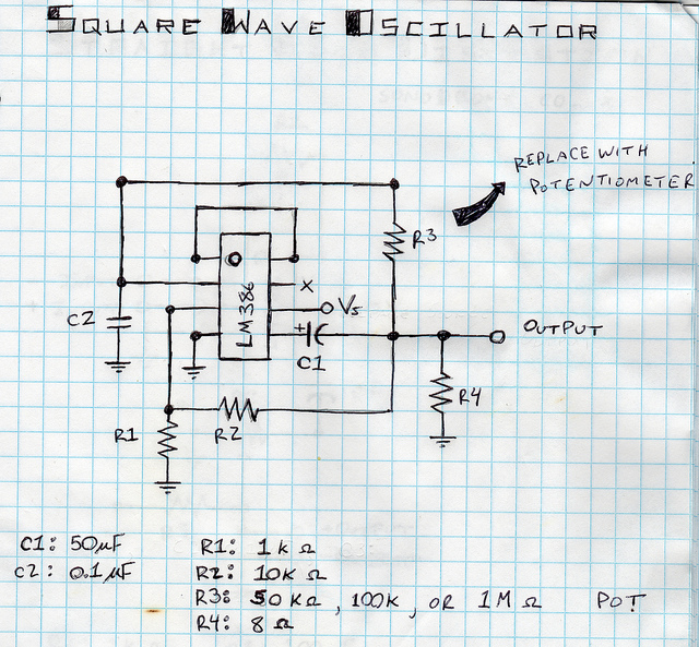
This is a square wave oscillator (digital, similar to 8-bit music). It is based on the LM386 amplifier integrated circuit, which is also the foundation for the mini guitar amplifier. The design includes a simple power switch connected to...
This oscillator is a variation of the oscillator presented by Ulrich L. Rohde, DJ2LR, in his article "Evaluating Noise Sideband Performance in Oscillators," published in Ham Radio, October 1978, Page 51. The original circuit can be found at the...
Design a Colpitts oscillator in a common collector configuration using a single BJT. Provide base current to ensure the transistor operates correctly, which can be achieved using a potential divider (between Vcc and ground). It is advisable to use...
The circuit was designed to create an electronic oscillator known as a Wien Bridge Oscillator, which can be used for the creation of low-frequency sine waves. The Wien Bridge Oscillator is a type of electronic oscillator that generates sine waves....