
Astable Multivibrator using transistors
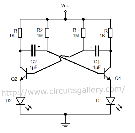
In a typical transistor switching circuit, the transistor operates in two states: saturation and cutoff. When the transistor is in saturation, it allows maximum current to flow from the collector to the emitter, effectively acting as a closed switch. Conversely, in the cutoff state, the transistor prevents current flow, acting as an open switch.
The circuit can be configured with various components such as resistors, capacitors, and additional transistors to create more complex switching applications. The base terminal of the transistor is controlled by an input signal, which determines whether the transistor is in the on or off state.
For instance, a resistor may be connected to the base to limit the current flowing into it, ensuring the transistor operates within its safe limits. The collector terminal can be connected to a load, such as an LED or motor, which will be activated when the transistor is in the saturation state.
Understanding the behavior of the transistor in this configuration is essential for designing reliable electronic circuits. Proper biasing and component selection are critical to ensure the transistor switches effectively and does not enter undesirable operating regions. Additionally, the characteristics of the transistor, such as its current gain (beta), must be considered when designing the circuit to achieve the desired output performance.We can also take output from collector terminals of the transistors, such circuit is show below. To know the working of below circuit you must read How transistor acts as a switch 🔗 External reference
Related Circuits

A car door differs from a calculator or a phone in that it makes sense to press more than one key at a time. The functionality of a car door can be compared to that of a multi-key input device,...

This circuit diagram illustrates a simple electronic combination lock utilizing the IC LS7220. The circuit is designed to activate a relay for controlling any device (turning it on and off) when a specific combination of four digits is entered....
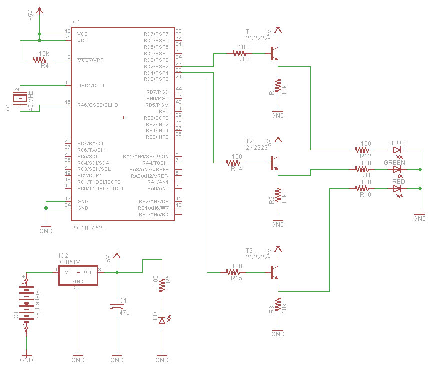
A very popular type of LED that has finally emerged is the tri-color, RGB LED. The RGB stands for red, green, and blue, as the LED is capable of displaying various colors through the combination of these three primary...

This document presents an application utilizing the Nokia 3310 LCD for designing a thermometer using the DS1621 temperature sensor IC. The DS1621 is an 8-pin sensor manufactured by Maxim. The circuit design involves integrating the DS1621 temperature sensor with a...

This liquid level sensor electronic circuit diagram utilizes a common CA3410 operational amplifier integrated circuit (IC). The sensor employs two plate sensors (or probes), one designated for detecting high liquid levels and the other for low liquid levels. If...
What exactly is a multivibrator? I suppose one definition would be 'a circuit which has several states'. This will do for now, it's quite loose so leaves plenty to the imagination! Conventional multivibrators have only two stages and come...
Warning: include(partials/cookie-banner.php): Failed to open stream: Permission denied in /var/www/html/nextgr/view-circuit.php on line 713
Warning: include(): Failed opening 'partials/cookie-banner.php' for inclusion (include_path='.:/usr/share/php') in /var/www/html/nextgr/view-circuit.php on line 713