
transistor as a switch circuit problems
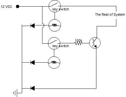
The proposed circuit configuration employs two key switches connected in series. In this arrangement, the current can only pass through the circuit when both switches are in the closed position. This design is commonly used in applications where a safety mechanism is required, ensuring that multiple conditions must be met before activating a load or system.
To construct the circuit, the following components are necessary:
1. **Power Source**: A suitable DC or AC power supply, depending on the application requirements, should be selected. The voltage rating must match the specifications of the load and switches.
2. **Key Switches**: Two key switches rated for the necessary voltage and current should be used. These switches should have a mechanism that requires a key to be inserted and turned to the 'on' position, providing an additional layer of security.
3. **Load**: The load can be any device or circuit that requires activation when both switches are closed. This could be a motor, light, or any other electronic device.
4. **Wiring**: Appropriate gauge wire should be used to connect the components. The wire gauge must be selected based on the current rating of the load to prevent overheating.
5. **Protection Components**: Depending on the application, it may be prudent to include a fuse or circuit breaker to protect against overcurrent situations. Additionally, diodes may be used for flyback protection if inductive loads are involved.
The circuit should be laid out such that the positive terminal of the power source connects to one terminal of the first key switch. The second terminal of the first switch connects to one terminal of the second key switch, and the other terminal of the second switch connects to the load. Finally, the load connects back to the negative terminal of the power source, completing the circuit.
Testing the circuit after assembly is essential to ensure that it operates as intended. A multimeter can be used to check continuity and verify that the circuit only allows current flow when both key switches are closed. Proper labeling and documentation of the circuit will aid in future maintenance and troubleshooting.Hi, I`m trying to build a circuit with two key switches, where both key switches need to be closed for the current to go through. I am trying to use a .. 🔗 External reference
Related Circuits
A good/bad transistor tester is an instrument designed to determine the operational status of a transistor, indicating whether it is functional or defective. This device provides a simple binary assessment, confirming if the transistor has a gain equal to...

This is a simple and cost-effective solar battery charger that can be constructed by hobbyists. It has some limitations compared to other similar controllers, but it also provides several benefits. While primarily designed for charging lead-acid batteries, it can...
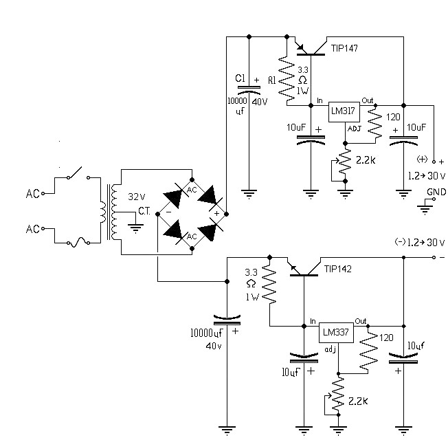
The 10A variable power supply circuit is symmetrical and can provide a symmetrical output voltage ranging from ±1.2 volts to ±30 volts DC, with a maximum current of 10A. This circuit utilizes symmetrical variable voltage regulators LM317 and LM337,...
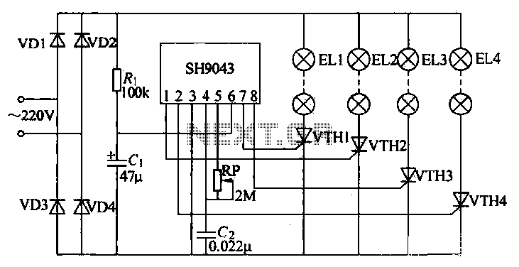
This example demonstrates a robust design featuring novelty lights that flash in a specific sequence, utilizing a 1-3-2-4 vault chase mode. The circuit includes diodes VD1 to VD4, which form a bridge rectifier, converting AC voltage to a full-wave...

This circuit functions as a voice transmitter utilizing a pair of BC548 transistors. While these transistors are not specifically designed for RF applications, they still yield satisfactory performance. An ECM microphone insert from Maplin Electronics, order code FS43W, is...

The RS-232 system connection is faster and easier, but the distance is limited. Therefore, this project involves using an RS-485 system with an RS-232 to RS-485 converter. The RS-232 to RS-485 converter project aims to extend the communication range and...
Warning: include(partials/cookie-banner.php): Failed to open stream: Permission denied in /var/www/html/nextgr/view-circuit.php on line 713
Warning: include(): Failed opening 'partials/cookie-banner.php' for inclusion (include_path='.:/usr/share/php') in /var/www/html/nextgr/view-circuit.php on line 713