
INA217 professional miniature microphone microphone circuit diagram of a typical preamp

The INA217 preamplifier circuit is designed for high-performance audio applications, particularly where low noise and accurate signal amplification are critical. The use of phantom power allows for powering condenser microphones, which are sensitive and require a stable power supply. The design ensures that the phantom power is isolated from the audio signal path, preventing any DC voltage from affecting the audio quality. The inclusion of capacitors C1 and C2 serves a dual purpose: they block any DC component while allowing the AC audio signal to pass through, ensuring that only the desired audio frequencies are amplified.
The choice of the OPA137 operational amplifier in the feedback loop is significant, as it provides a low noise and low distortion output, essential for maintaining audio fidelity. The feedback mechanism is crucial for stabilizing the gain and reducing output offset, which can be particularly important in sensitive audio applications. The gain setting resistors R6 and R7 allow for flexibility in adjusting the amplification level, accommodating various microphone sensitivities and input signal levels. The antilog potentiometer configuration for R7 enables precise control over the gain adjustments, making it easier to achieve the desired output level without introducing unwanted noise or distortion.
Overall, this preamplifier circuit is suitable for professional audio equipment, ensuring high-quality sound reproduction while providing the necessary features for versatility in different audio environments. The careful selection of components and the design of the circuit layout contribute to its effectiveness in capturing and amplifying audio signals with minimal interference and maximum clarity. As shown in FIG constituted by INA217 professional miniature microphone (microphone) typical preamp circuit. FIG set a switch for selecting whether the choice of phantom power function, when the switch connected to + 48V when the choice of phantom power function, when the switch to the resistor R3 is prohibited phantom power. Elected to use phantom power feature, + 48V power supply through R1, R2 was added 3,2 socket contacts, providing a current path.
The socket is left and right channel mix outlet, therefore + 48V phantom power through the power socket to the distal miniature microphone (microphone) power supply. After the distal end of the miniature microphone (microphone) voice signal input through the socket after the INA217 amplifier output.
C1, C2 isolates phantom power power supply DC voltage into the INA217, while coupling the AC signal. If instead of phantom power, C1, C2 available nonpolar capacitors. R4, R5 provide access INA217 input bias current, and input offset current (typical 100nA) produces a DC differential voltage, the DC differential voltage at the output terminal will generate output offset voltage, output offset at maximum gain G 1000 (60dB) when voltage may be a few volts. This is generally acceptable, because the output using the AC coupling due to the blocking effect of the coupling capacitor, the output offset voltage does not affect subsequent circuit stages.
Cheap OPA137 operational amplifier feedback loop for driving the DC output voltage to 0V, since the audio channel OPA137 not, it will not affect the signal quality. R6 is used to set the maximum gain, the gain can be varied to adjust R7, R6 and R7 of the total resistance determines the minimum gain.
The effect of changes in linear dB usually R7 selected antilog potentiometer can generate a rotation.
Related Circuits
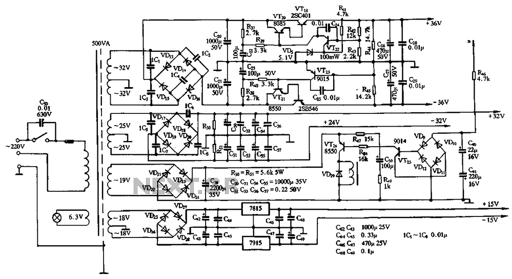
The power supply circuits for servo systems are critical during both the adoption and operational stages. The power supply circuit for servo systems is designed to provide stable and adequate voltage and current levels necessary for the servo motors to...
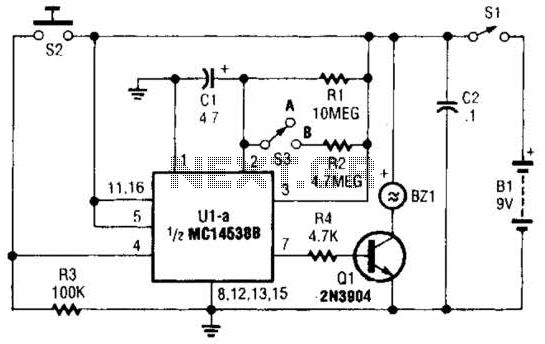
This circuit emits a loud tone if the input switch (S2) is not retriggered at designated intervals. If the user falls asleep and fails to re-trigger the circuit, it will continue to sound until S2 is pressed. The circuit operates...
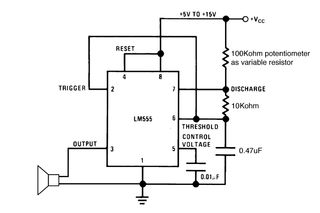
Setting the 555 timer in astable mode results in a continuous series of output pulses. The 555 timer IC, when configured in astable mode, operates as an oscillator, generating a square wave output. This configuration does not require any...

This design schematic illustrates a Crystal Colpitts oscillator that can be implemented using a transistor and a parallel mode crystal. In this circuit, the crystal functions as an inductance. A large value capacitive divider is utilized between the gate,...
The IR Jammer is a fun project that provides a bit of safe, non-destructive fun. The Infrared Remote Control Jammer allows you to render all IR remote controls inoperative! The microcontroller in this design allows for all 6 of...
This circuit provides a digital square wave that can be viewed directly or used to drive other circuits. It used the CMOS 4047 Low-Power Monostable/Astable Multivibrator. As used in Tom Duncan's Adventures with Digital Electronics Book, to drive CMOS...