
Increased Feedback-Stabilized Amplifier
The current-feedback amplifier is a versatile component widely used in applications requiring efficient signal processing, particularly when driving capacitive loads. In traditional implementations, a series resistor isolates the capacitive load from the amplifier, which can limit performance. By employing feedback resistors exclusively, the design can be optimized for a range of capacitive loads without the need for additional components.
The feedback resistance RF is critical in defining the amplifier's bandwidth. A higher RF value leads to a narrower bandwidth, which enhances stability and performance when driving capacitive loads. This characteristic is particularly beneficial in applications where load capacitance can vary significantly, allowing for greater flexibility in design.
The feedback resistor RG, on the other hand, is responsible for setting the gain of the amplifier. The gain must be carefully balanced with the feedback resistance to ensure optimal performance across the desired frequency range.
To accurately determine the relationship between RF and the capacitive load, empirical testing is recommended. By starting with the manufacturer's suggested value for RF, one can establish a baseline frequency response. Gradual increments of capacitive loading will reveal the maximum capacitance the amplifier can handle before performance degradation occurs, typically indicated by a peak in the frequency response.
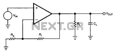
This iterative testing approach allows for the creation of a graph that correlates feedback resistor values with capacitive load capabilities, providing a valuable reference for engineers designing circuits that incorporate current-feedback amplifiers. Such data can significantly enhance the reliability and performance of electronic systems, particularly in high-frequency applications where capacitive effects are pronounced. The usual method for using a current-feedback amplifier to drive a capacitive load isolates the loa d with a resistor in series with the amplifier"s output. A better solution involves only the amplifier"s feedback resistors (Fig. 58-3(a)). Because the feedback resistors determine the amplifier"s compensation, you can select the optimal value for these feedback resistors for almost any capacitive load. Feedback resistance RF sets the amplifier"s bandwidth. Increasing RF reduces the amplifier"s bandwidth, which significantly improves the amplifier"s ability to drive capacitive loads.
Feedback resistor RG sets the amplifier"s gain. You cannot get the data necessary to calculate alternate values for RF from most data sheets. However, a few minutes at the bench with a network analyzer will generate the data to make a graph of the value of the feedback resistor vs. the amount of capacitive load the amplifier can drive (Fig. 58-3(b)). Start with the recommended data-sheet value for feedback resistor RF and measure the amplifier"s frequency response without any capacitive load.
Note the bandwidth, then add capacitive loading until the response peaks by about 5 dB. Record this value of capacitance; it is the maximum amount for that feedback resistor. Then, increase the value of the feedback resistor and repeat the procedure until you develop a graph like the one in diagram. 🔗 External reference
Related Circuits
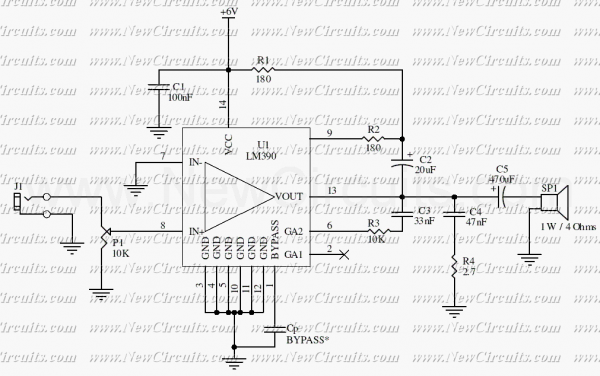
This circuit is a mono audio amplifier that will boost low frequencies as you see at the frequency response. The circuit is suitable for driving a subwoofer speaker for example. The output power of the circuit is about 1...
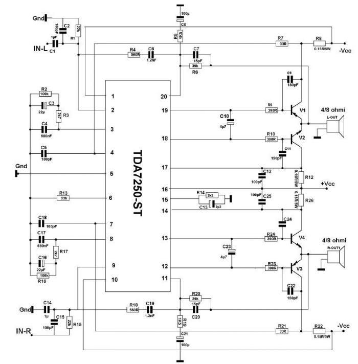
The TDA7250 audio driver, manufactured by SGS Thomson, can be utilized to design a straightforward high-power audio amplifier project with minimal external components. This audio amplifier can operate with either a 4-ohm or an 8-ohm load, delivering a maximum...
This balanced preamplifier circuit is designed to amplify low-level audio signals (from 0 dB to 20 dB) and features balanced inputs and outputs. The design utilizes standard components that are readily available in the electronics market. The balanced preamplifier circuit...
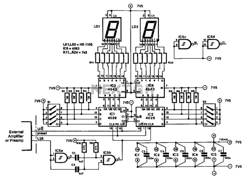
The indicator is designed for use with an audio amplifier or preamplifier, but it can also be utilized in other applications requiring rapid counting of steps or changes. To avoid interference with the audio signal, the circuit operates in...
This HD TV UHF wideband amplifier (Ultra High Frequency amplifier) provides a total gain of 10 to 15 dB within the frequency range of 400 to 850 MHz, making it suitable for areas with weak television signals. To ensure...
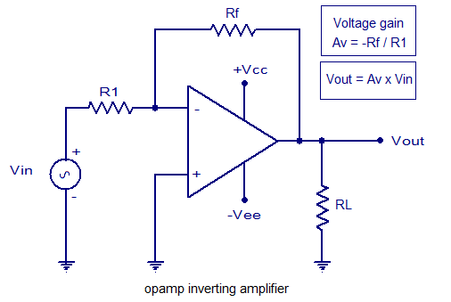
An inverting amplifier utilizing an operational amplifier (op-amp). This includes equations for voltage gain and output voltage, as well as input and output waveforms, and a practical inverting amplifier circuit using the 741 IC. An inverting amplifier is a fundamental...