
Wideband DTV UHF Antenna TV Amplifier Circuit using transistor 2sc3358
The HD TV UHF wideband amplifier is designed to enhance the reception of television signals in the UHF frequency range, specifically between 400 MHz and 850 MHz. This frequency range is critical for receiving various digital and analog television broadcasts. The amplifier's gain of 10 to 15 dB is significant enough to boost weak signals, improving the overall quality of the received television content.
To maximize the effectiveness of the amplifier, it is crucial to minimize the length of the component leads. Longer leads can introduce unwanted inductance and capacitance, which can degrade the amplifier's performance and introduce noise into the signal. The use of SMD components, such as C1, C2, C6, and C7, facilitates a compact design and allows for shorter connections, further enhancing signal integrity.
The requirement to enclose the amplifier in a metal box is essential for shielding against electromagnetic interference (EMI) and radio frequency interference (RFI). This shielding helps maintain the quality of the amplified signal by preventing external noise from corrupting the transmission. Furthermore, placing the amplifier close to the TV antenna reduces the length of the coaxial cable required, which can also contribute to signal loss.
In summary, the design and implementation of the HD TV UHF wideband amplifier involve careful consideration of component selection, layout, and housing to achieve optimal performance in enhancing weak television signals. Proper assembly and installation are critical to ensure that the amplifier functions effectively within its specified frequency range.This HD TV UHF wideband amplifier (Ultra High Frequency amplifier ) has a total gain of 10 to 15 dB in the 400 850 MHz domain frequency so it can be used where the tv signal is weak. For this UHF antenna tv amplifier to work correctly you need to cut the components pins as short as possible.
C1, C2, C6, C7 are SMD type ( surface mounted ). Thi s antenna tv amplifier or uhf wideband amplifier need to be build inside of a metal box and then connected close to the tv antenna. 🔗 External reference
Related Circuits
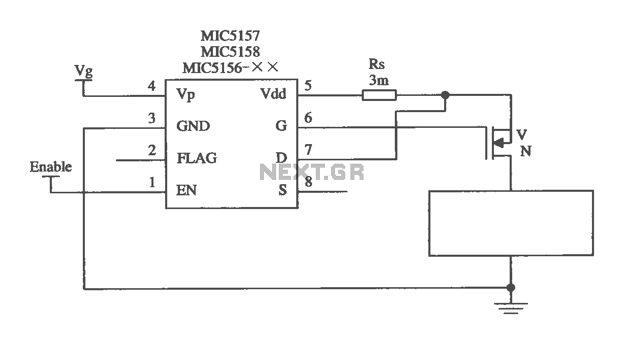
The MIC5156 is a device that incorporates a current limiting function, allowing it to handle high output currents. It can operate with or without a switching regulator circuit. The S terminal is left vacant, and a 16V Zener diode...
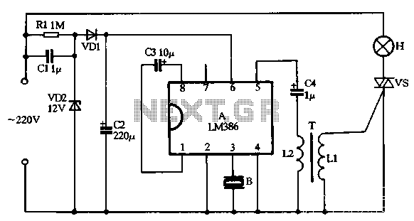
VD1, VD2, C1, and C2 comprise a simple half-wave rectifier capacitor step-down voltage regulator circuit, providing an output of approximately 12V for a linear power supply connected to the LM386. The LM386 is linked to the inverting input terminal...
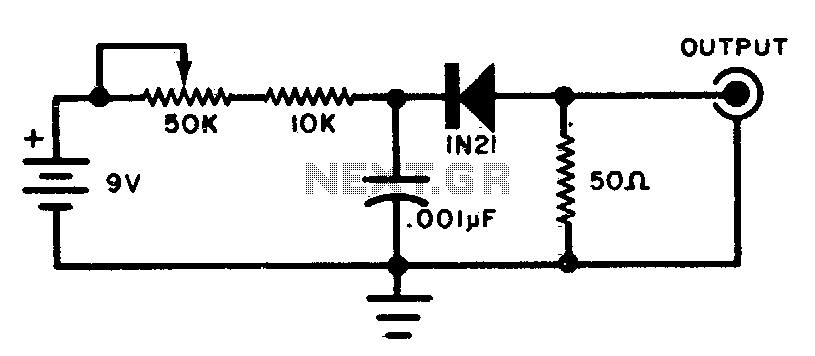
This circuit generates wideband RF noise utilizing a reverse-biased diode, featuring a low-impedance output. It can be employed to align receivers for optimal performance. The circuit primarily consists of a reverse-biased diode, which serves as the core component for generating...
Frequency-Shift Keying (FSK) is a type of frequency modulation where the modulating signal alters the output frequency between specific predetermined values. When issues occur during the demodulation of FSK signals, utilizing an FSK filter circuit can be beneficial. Frequency-Shift Keying...
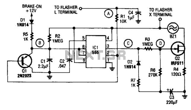
The STS schematic illustrates a circuit designed to alert a driver when the turn signal has been active for more than 15 seconds. The voltage at the gate of transistor Q2 increases in response to the charge accumulated on...

This simple temperature relay circuit can be used to signal a fire or setpoint for temperature monitoring function. You need to adjust P1 so that T1's base. The temperature relay circuit operates by monitoring the temperature in a designated area...