
Increasing Output Voltage of a Fixed Linear Regulator
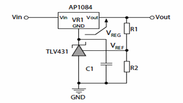
The schematic in question employs a fixed linear regulator, which typically provides a stable output voltage but may lack the precision required for sensitive applications. By integrating a 3-terminal shunt regulator, the overall voltage regulation can be improved significantly. The 3-terminal shunt regulator operates by shunting excess current away from the load, thus maintaining a constant output voltage despite variations in input voltage or load conditions.
In the configuration, the fixed linear regulator is connected to the input voltage source, and its output is fed into the input of the 3-terminal shunt regulator. The shunt regulator is designed to maintain a specific output voltage by adjusting its shunt current in response to changes in load or input voltage. This feedback mechanism allows for precise voltage regulation, making it particularly suitable for applications requiring tight voltage tolerances.
The output of the shunt regulator can be set to a desired voltage level by selecting appropriate resistor values in the feedback network. This flexibility allows for customization of the output voltage to meet specific circuit requirements. The inclusion of bypass capacitors at the output of the shunt regulator is also recommended to filter out any high-frequency noise, thereby ensuring a clean and stable output voltage.
Overall, this schematic demonstrates an effective approach to enhancing the performance of a fixed linear regulator, providing a reliable solution for applications where precision voltage regulation is critical.The following schematic shows how to Increase Output Voltage of a Fixed Linear Regulator Circuit Diagram using 3-terminal shunt regulators or references. The 3-terminal shunt regulators provide their precision function to turn the medium accuracy linear regulators into precision ones
🔗 External reference
Related Circuits
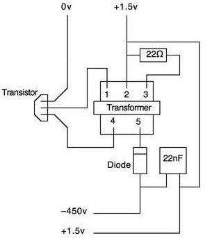
This article outlines a straightforward and effective method for deterring intruders. While alternative methods exist, this approach is suitable for office pranks and general amusement. The project necessitates a basic understanding of electronics and circuitry, including the ability to...
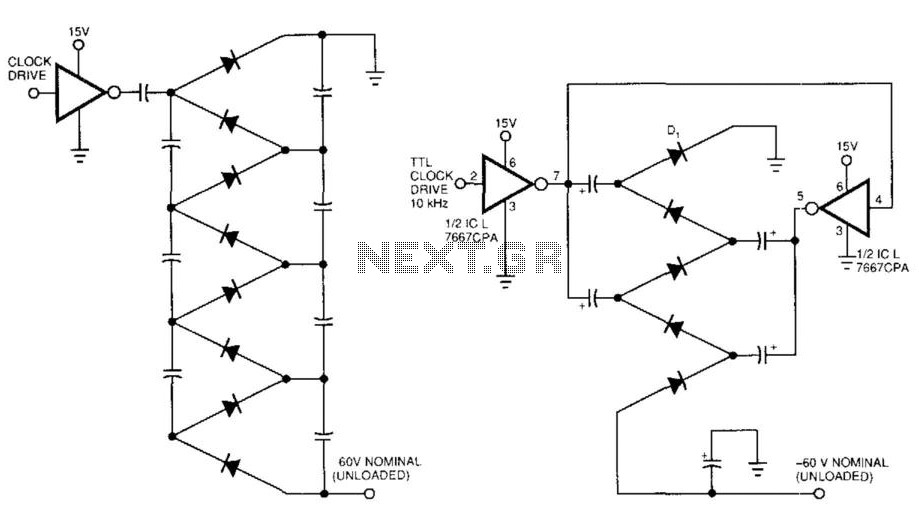
Figure 99-1(a)'s circuit exhibits a high output impedance due to the small effective capacitance of the series-connected capacitors, resulting in considerable voltage loss from the diode drops. This circuit requires two diodes and two capacitors to generate a DC...
This device is a successor to the PIC16C71 4-digit LED frequency counter and voltmeter. It omits some hard-to-find components from the previous version that have been out of production for some time. The earlier PIC16C71 has been replaced with...
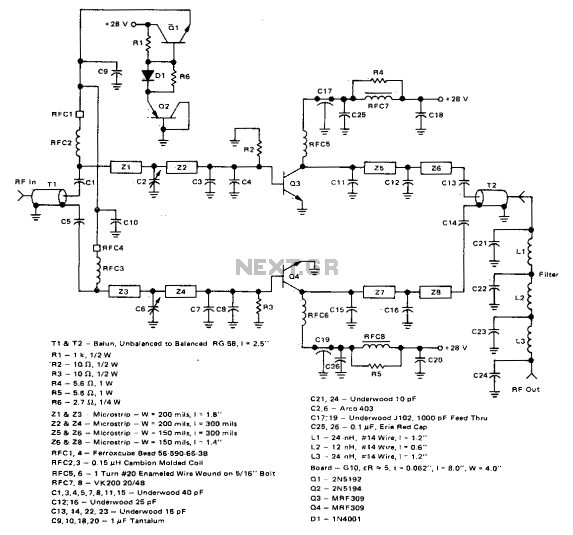
This 100-watt linear amplifier can be built using two MRF309 transistors in a push-pull configuration, requiring only 16 watts of drive power within the frequency range of 420 to 450 MHz. It operates from a 28-volt supply and achieves...
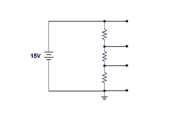
Ground serves as a reference point for the voltage divider, with each successive point above ground indicating the voltage drop across the circuit. For example, with a 15-volt input and 5K ohm resistors, the voltage taps would measure 5,...
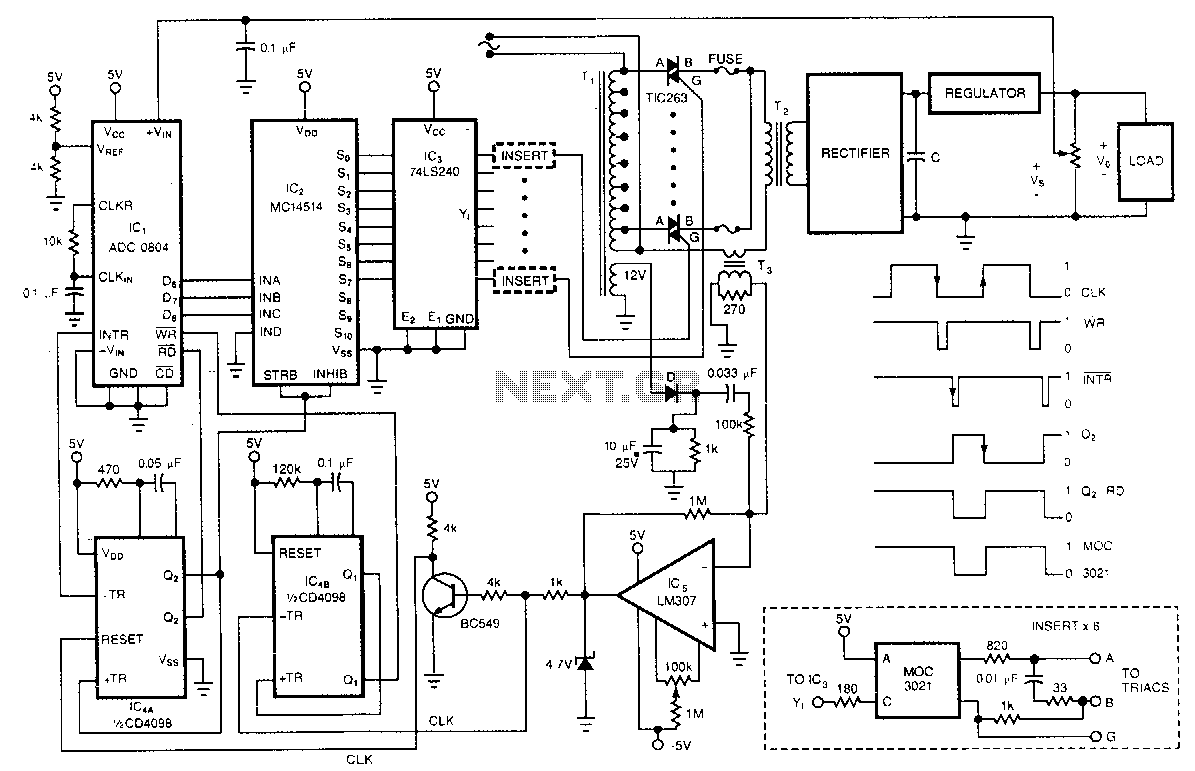
One of the control circuit's triacs selects the tap on the main transformer T1, which provides the proper preregulated voltage to the secondary regulator. T2 and its associated components comprise the secondary regulator. The ADC 0804, IC1, digitizes a...