
Reading a voltage divider schematic
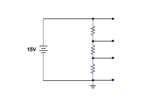
In a voltage divider circuit, the arrangement typically consists of two or more resistors connected in series across a voltage source. The voltage across each resistor can be determined by the principle of voltage division, which states that the voltage drop across a resistor in series is proportional to its resistance relative to the total resistance of the circuit. The ground reference is crucial in establishing a common point for measuring voltages throughout the circuit.
When ground is connected at a specific point in the circuit, it does not mean that all current will flow directly to ground. Instead, the current will distribute according to the resistances in the voltage divider. In the described scenario, with a 15-volt input and two 5K ohm resistors, the voltage across each resistor will be calculated using the formula:
V_out = V_in * (R2 / (R1 + R2))
Where:
- V_out is the voltage across R2,
- V_in is the input voltage (15 volts),
- R1 and R2 are the resistances of the two resistors (both 5K ohms in this case).
For the first resistor (R1), the voltage drop can be calculated as follows:
V_R1 = 15V * (5K / (5K + 5K)) = 15V * (5K / 10K) = 7.5V
For the second resistor (R2), the voltage drop will be:
V_R2 = 15V * (5K / (5K + 5K)) = 15V * (5K / 10K) = 7.5V
Thus, the total voltage drop across both resistors adds up to the input voltage of 15 volts. The voltage at the junction between the two resistors (the tap points) will measure 7.5 volts, which is half of the input voltage, confirming the operation of the voltage divider.
The current flowing through the circuit is determined by Ohm's Law (I = V/R). In this case, the total current flowing through the series circuit can be calculated as:
I_total = V_in / (R1 + R2) = 15V / (5K + 5K) = 15V / 10K = 1.5 mA
This current flows through both resistors, and the voltage drops across each resistor create the desired tap voltages. The presence of ground does not create a short circuit; rather, it provides a reference point for the voltage measurements and allows the circuit to function as intended without sinking all current to ground. Proper understanding of the voltage divider configuration and the role of ground is essential for effective circuit design and analysis.Ground is used as a reference for the voltage divider, and that each successive point above ground is how much voltage is dropped across the circuit. (So with a 15 volt input, and 5K ohm for each resistor the taps would be 5, 10, and 15 volts respectively.
) What I do not understand is by placing ground at that location, wouldn`t you immediately sink all the current to ground and have nothing moving through the voltage divider As I understand it, current will move to either ground or a more positively charged location (such as the positive side of a battery in this case), but with ground located where it is I do not understand why all current would not immediately sink to ground vice the voltage divider. Please let me know if this is just a poorly developed example or where my misunderstanding is. 🔗 External reference
Related Circuits
According to the note on the schematic, IC-2 is a 74HC74 TTL chip. Refer to the data sheet for details regarding pins 7 and 14. The note for IC-3, located lower on the schematic, indicates it is an AC...
This is a specialized low-voltage version of an audio preamplifier. The emitter voltage of transistor T1 is biased close to half the supply voltage (1.5V) to enable maximum output voltage swing. Both transistors are directly coupled and utilize closed-loop...
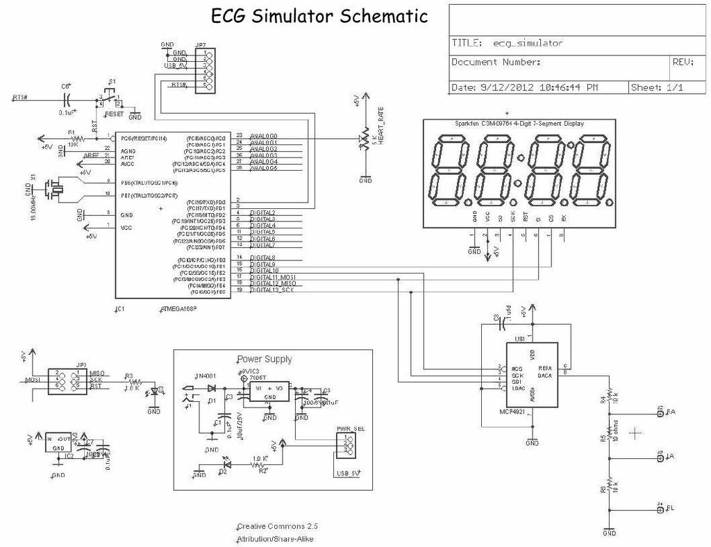
Below is the final schematic for the Menta ECG Simulator project. LadyAda's Eagle schematic for the Menta was used as a starting point. The Menta ECG Simulator project is designed to emulate the electrical signals produced by the heart, providing...
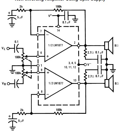
This audio amplifier circuit is designed to deliver 2W per channel continuously into 8-ohm loads. The LM1877 is engineered to function with a minimal number of external components while still offering flexibility for applications in stereo phonographs, tape recorders,...

This is a 50-watt audio power amplifier circuit based on the single IC STK4036II. A heatsink is required to prevent overheating of the IC. The amplifier circuit provides good sound quality at an affordable price and is easy to...
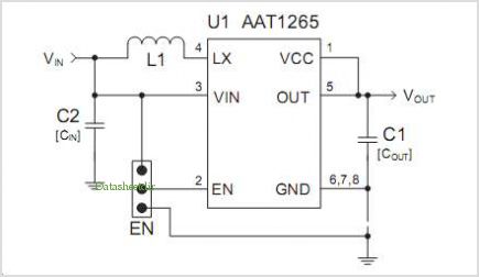
The AAT1275 evaluation board serves as a platform for testing and evaluating the AAT1275 switching boost converter equipped with a USB power switch. This evaluation board showcases the recommended size and placement of external components to achieve 5V output...