
Increasing the power rating of zener diodes
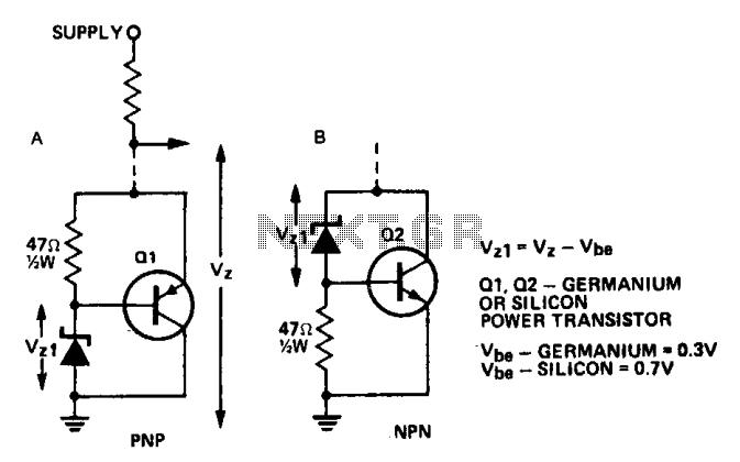
The described circuit configuration employs a power transistor to amplify the Zener voltage output, allowing for the use of lower-rated Zener diodes in applications that demand higher power levels. The selection of transistors is critical: for lower power requirements, the ASZ 15 or AY9140 are suitable choices for Q1, while the 2N2955 serves as a robust option for Q2. In contrast, for higher power demands, the ASZ18 or 2N2955 can be used for Q1, with Q2 being fulfilled by either the 2N3055 or AY8149, both of which are capable of handling increased current loads.
The integration of a heatsink is essential for thermal management, as power transistors dissipate significant heat during operation. The design allows for the transistors to be mounted directly onto a metallic chassis, which not only secures the components but also enhances heat dissipation by utilizing the chassis as a passive heatsink. This configuration promotes efficient thermal management, ensuring the reliability and longevity of the circuit by preventing overheating.
Overall, this circuit design exemplifies an effective method to achieve higher power Zener voltage outputs while maintaining manageable thermal conditions through careful component selection and efficient heatsinking strategies.A power transistor can be used to provide a high powered zener voltage from a low wattage zener. A 400 mW zener can be used where a 10 watt zener is required or a 1 W zener can be used where a 50 to 80 watt zener is required by using appropriate transistors for Ql and Q2 in the circuits shown. Where low rating is required, Ql would be an ASZ 15 (germanium) or an AY9140 (silicon). Q2 could be a 2N2955 (silicon). For higher powers, Ql should be an ASZ18 (germanium) or a 2N2955 (silicon) and Q2 a 2N3055 (silicon) or an AY8149 (silicon).
A heatsink on the transistor is required. The circuit in A has the advantage that power transistors can be bolted directly on to a chassis which may serve as a heatsink. 🔗 External reference
Related Circuits
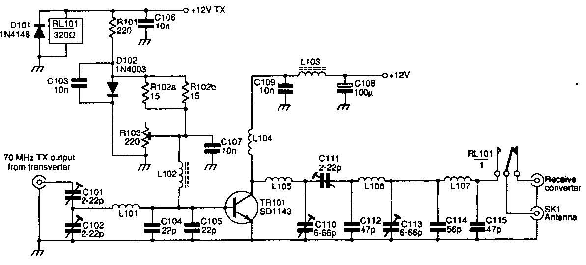
This 70 MHz RF power amplifier circuit utilizes the SD1143 transistor, which offers a gain of approximately 14 dB in this configuration. The design leverages the characteristics of a 175 MHz device. The RF power amplifier circuit designed around the...
The Electronics Schematic Diagram MJR7-Mk3 Mosfet MJR6 page includes distortion extracted using the nulling method with a speaker load and a music signal to demonstrate that these designs have no audible distortion in normal use. The MJR7 has even...
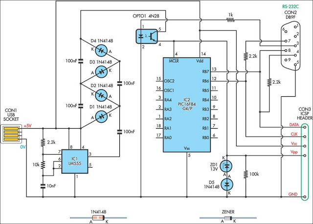
This simple circuit can be used to program the PIC16F84 and similar flash memory type parts. It uses a cheap 555 timer IC to generate the programming voltage. The circuit utilizes a 555 timer IC configured in astable mode to...

The input capacitor is used for low-frequency cut-off, with a standard value of 0.1 µF, resulting in a cut-off frequency of approximately 16 Hz. The input capacitor plays a critical role in electronic circuits, particularly in signal processing and audio...
The 7815 regulates the positive supply, while the 7915 regulates the negative supply. The transformer should have a primary rating of 240/220 volts for Europe or 120 volts for North America. The center-tapped secondary coil should be rated approximately...
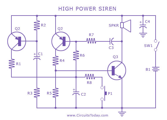
A siren circuit diagram that generates a strong, high-power siren or alarm sound using complementary transistor pairs BC 557 and BC 337, arranged as an oscillator. The described siren circuit employs a pair of complementary transistors, BC 557 (a PNP...