
GSM Remote Control 2 IN and 2 OUT Part 2 Schematic

The schematic design incorporates a robust power management system that ensures stable operation across a wide voltage range. The use of a switching regulator allows for efficient power conversion, minimizing heat generation and maximizing reliability. The inclusion of multiple capacitors for filtering ensures that voltage spikes do not interfere with the microcontroller's operation, which is critical for maintaining the integrity of communication with the GSM module.
The microcontroller's firmware is designed to efficiently manage I/O operations, ensuring timely responses to incoming calls and messages. The opto-isolated inputs provide electrical isolation, enhancing the system's resilience to external interference. The design also allows for flexibility in firmware development, with options to utilize an external oscillator for applications requiring precise timing.
In terms of communication, the UART interface facilitates seamless data exchange between the microcontroller and the GSM module, accommodating various control signals that enhance the reliability of message transmission and reception. This comprehensive design approach ensures that the system remains responsive and functional, even in challenging operational environments. The integration of protection components, such as fuses and diodes, further enhances the durability and safety of the circuit, making it suitable for a wide range of applications in automated control systems.The entire control is handled by a Microchip PIC18F46K20-I/PT microcontroller, programmed with a firmware that controls the GSM/GPRS module`s activity, reads the logic condition of the two opto-isolated inputs and sends commands to the two relays in the device. Having said that, let`s take a better look at the electrical scheme: power is supplied by continuous voltage, not always stabilized (applied to PWR, + and -) at a value between 5 and 32 V; such voltage is filtered at the bottom by the diode protecting against polarity inversion (D1) through condensers C1 and C2. Fuse F1 enables you to protect both the circuit and the power source in case of short circuit in the integrated regulator discussed below, which is necessary to obtain the 3.
6 V, needed for the rest of the circuit to work. The switching regulator U1 is based on a MC34063 chip, used in the classic configuration of the PWM regulators series, charged by inductance, whose output voltage depends on the energy stored in L1; the regulator is stabilized by the component demoted from resistive divider R2/R3, which is needed to set the output tension at 3. 6 V. The impulses produced by the inducer`s switching are then leveled by condensers C4 and C5. The 3. 6 volts at the bottom of the above mentioned condensers are then filtered by other condensers placed on the power lines of the microcontroller and of the GSM module; which presents, during transmission, absorption peaks compensated for by C7, C8, C13, C14, C15 and C16, thus avoiding that an impulsive current request may cause the microcontroller to be disturbed.
The PIC is used in the configuration with an internal clock oscillator; both the scheme and the printed circuit are nevertheless equipped with external quartz, intended for those who want to modify the firmware and develop applications requiring an external oscillator. Once the I/O lines have been initialized, the microcontroller verifies the logical state of the opto-isolated inputs at voltage level (RB4 and RB5) as well as that of lines RC4, RC5, RD0, RD3, RX, which are needed to receive the main notifications from the cellular module; more specifically, RD3 is used to detect incoming calls (it interfaces with RI of the cellular module), while RC4 controls the GSM field LED , whose output (dubbed LED) pulses at a frequency of 1 Hz when the module is searching for the radio-mobile network, and supplies impulses at logical zero, lasting 0.
5 seconds, followed by a 2-second pause, when the module has grasped the signal. The frequency and duration of the impulses enable the PIC to understand the conditions of the radio-mobile network range and to behave accordingly; for example, if the opto-isolated input goes off and therefore needs to send SMS or make calls, but detects that the cellular module has no reception, it waits for the module to get reconnected to the GSM/GPRS network before making any calls. The microcontroller contains a UART accessible via pins 44 (transmission) and 1 (reception) which it uses in order to communicate with the mobile; more precisely, through the first pin (TX), it cyclically questions the module to check whether any SMS has been received, whereas both TX and RX are used for the communication between the microcontroller and the GSM module when making calls and receiving or sending messages.
Regarding the UART, the following control signals are used: CTS (Clear To Send), RTS (Request To Send) and DCD (Data Carrier Detect), which correspond to those of the cellular module being used. Lines RC5 and RD0 complete the set of I/Os destined to the mobile; the former controls the turning on and off of the GSM (through a transistor placed in the small board of the mobile), the latter takes care of resetting the mobile.
The button for locally handling this device`s operating mode is read through line RA3, set as input and equipped with an external pull-up resistor (R11), therefor 🔗 External reference
Related Circuits
A switch-mode power supply provides ±15V or ±12V at 0.5A output from a 4.5V to 12V input. The wide input voltage range allows flexibility to be powered from a regulated DC voltage. The switch-mode power supply (SMPS) described operates within...
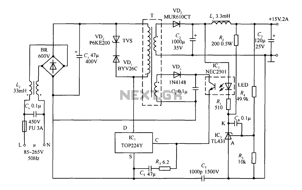
This circuit comprises a 15V TOP224Y, 2A output DC switching power supply. It utilizes three integrated circuits: IC1 is a monolithic regulator (TOP224Y), IC2 is an optocoupler (NEC2501), and IC3 is a precision voltage reference (TL431). The TL431 (IC3)...
Currently, a basic MOSFET amplifier or power amplifier is designed to deliver an output power of ±100 Watts RMS with an 8 Ohm load, or ±160 Watts RMS with a 4 Ohm load. The simplicity of this circuit results...
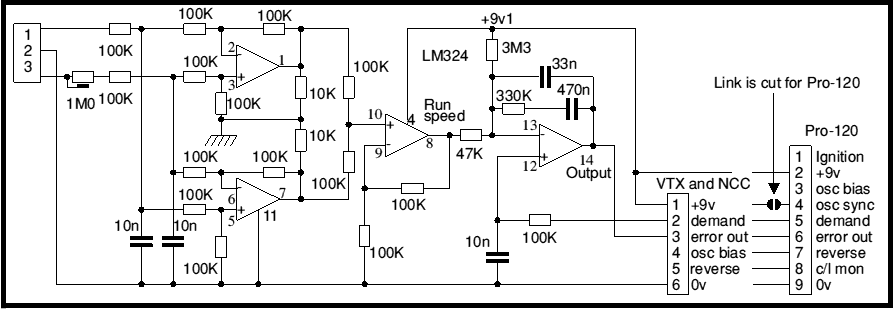
Most battery motor speed controllers are under manual control and the operator automatically adjusts speed to match demand. Under these conditions closed loop motor speed control is an unnecessary expense. However, when it is required, a tachogenerator can easily...
4 Channel Infrared (IR) Remote is a simple kit using the famous HT12A and HT12D encoder/decoder chips from Holtek. The 4 Channel Infrared (IR) Remote system utilizes the HT12A and HT12D integrated circuits to facilitate wireless communication between a transmitter...
A simple forward-reverse motor control driver electronic circuit can be designed using the LB1948M, a two-channel low saturation voltage forward-reverse motor control driver IC. The LB1948M motor driver is suitable for use in 12V system products and can drive...