
Infa-red Remote Control
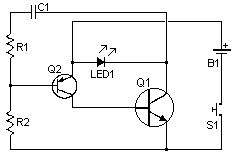
The infrared remote control circuit comprises several key components that work together to transmit and receive signals effectively. The primary component of the transmitter is the infrared LED, which emits infrared light modulated at a specific frequency to represent the desired tone. This modulation can be achieved using a simple oscillator circuit, which generates a square wave signal that drives the LED.
The oscillator circuit typically consists of a 555 timer IC configured in astable mode. Resistors and capacitors are selected to set the frequency of oscillation, which corresponds to the tone that the receiver will detect. The output from the 555 timer is connected to the anode of the infrared LED, while the cathode is grounded. A current-limiting resistor is also included in series with the LED to prevent excessive current flow, which could damage the LED.
On the receiving end, the infrared signals are detected by a photodiode or a phototransistor, which is sensitive to the frequency of the transmitted tone. When the phototransistor receives the modulated infrared light, it conducts, allowing current to flow through to the output stage. The output can be connected to a microcontroller or a relay, which can be used to control other devices based on the received signal.
To ensure reliable operation, the receiver circuit may incorporate a bandpass filter that allows only the specific frequency of the transmitted tone to pass through, rejecting other ambient light interference. This filter can be implemented using passive components such as capacitors and inductors or active components like operational amplifiers.
Overall, this infrared remote control system offers a robust solution for wireless communication, minimizing the chances of unintended activations through its tone-based encoding and decoding mechanism.I have received a number of emails requesting schematics for infa-red remotes. So here is one. This remote transmits a tone using an infa-red LED. This tone is decoded by the receiver. Since the receiver only switches when it "hears" the tone, there are no accidental activations. 🔗 External reference
Related Circuits

A combined monostable multivibrator using the 555 timer integrated circuit, along with a pair of light control comparators. This circuit can be utilized to control a load based on the timing parameters set within the circuit. The circuit comprises a...
A couple of motors were salvaged from an old printer, and there is uncertainty regarding how to connect them to a breadboard and subsequently to a Raspberry Pi. A cobbler kit for the Raspberry Pi is available for this...
The circuit depicted in Figure 3-80 is responsible for controlling a portion of the transistor multivibrator. A multivibrator serves as a robust positive and negative feed-forward amplifier, consisting of two branches that are interconnected through a coupled RC timing...

This is a three-mode lamp dimmer circuit with touch control. This circuit can be used to control a lamp in three operation modes: dim, off, and bright. It utilizes a NE555 timer. The three-mode lamp dimmer circuit designed with touch...

A simple oscillator circuit that varies the duty cycle over a wide range without affecting the frequency. It is a variation of the simple 555 astable oscillator. The use of an air-variable capacitor for frequency control is innovative. When...

The core of the switch controller is an Arduino Nano microcontroller, which will serve as the interface between the dashboard switches, wireless steering wheel buttons, and the vehicle's lighting, indicators, windscreen wipers, and DigiDash2 GPS stopwatch. This setup facilitates...