
Monostable circuit diagram of a light control
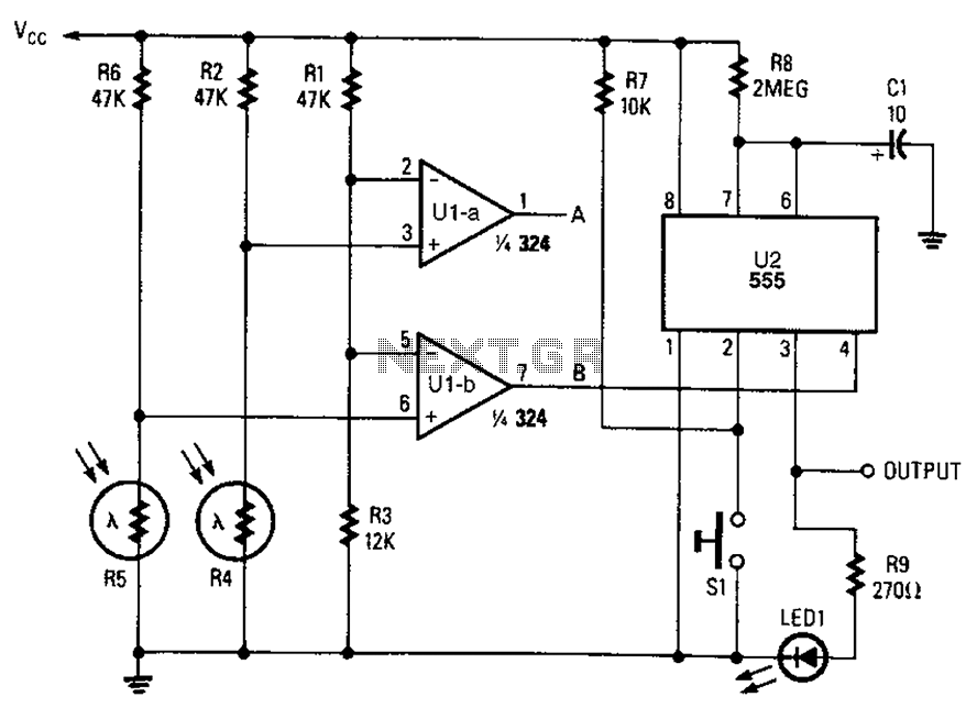
The circuit comprises a 555 timer configured in monostable mode, which generates a single output pulse in response to a triggering input. The duration of this pulse is determined by external resistors and capacitors connected to the timer. A pair of light control comparators are integrated into the design to monitor ambient light levels. These comparators provide the necessary feedback to the 555 timer, enabling or disabling its output based on the light conditions.
During daylight hours, the operation of the timer (U2) is disabled, ensuring that no output is generated. This prevents unnecessary power consumption by the load when ambient light is sufficient. As the light levels drop, the comparators detect the change and trigger the 555 timer, allowing it to produce an output pulse. The output can then be used to activate a load, such as a light fixture, ensuring that it operates only when required, thereby enhancing energy efficiency.
The circuit design allows for adjustable timing intervals, which can be fine-tuned by varying the resistor and capacitor values. This flexibility makes the circuit suitable for a variety of applications, including outdoor lighting systems, automatic night lights, and other scenarios where light level control is desired. The integration of the 555 timer with light control comparators provides a robust solution for automated load management based on environmental conditions. Combined monostable multivibrator 555 and a pair of light control and light control comparator monostable phase. Depending on the time of the circuit can be used to enable load device operation. During the day, the timer U2, is disabled, it does not produce any output. It produces no output.
Related Circuits
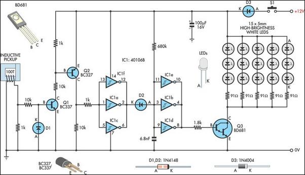
A timing strobe can be constructed using high-brightness LEDs and a few common components. Ignition pulses from the number one cylinder high-tension lead are used to trigger the circuit via a homemade inductive pickup. Transistors Q1 and Q2 buffer...
It is essentially a standard Hartley oscillator, with an output of +7 dBm into 50 Ohms. It is advised against adding a gate diode, as this circuit does not require it and such an addition would degrade phase noise...

This simple circuit is designed to check transistors, allowing measurements down to 40 ohms across the collector-base or base-emitter junctions. It is also capable of testing output power transistors in amplifier circuits. The circuit operates with a 555 timer...
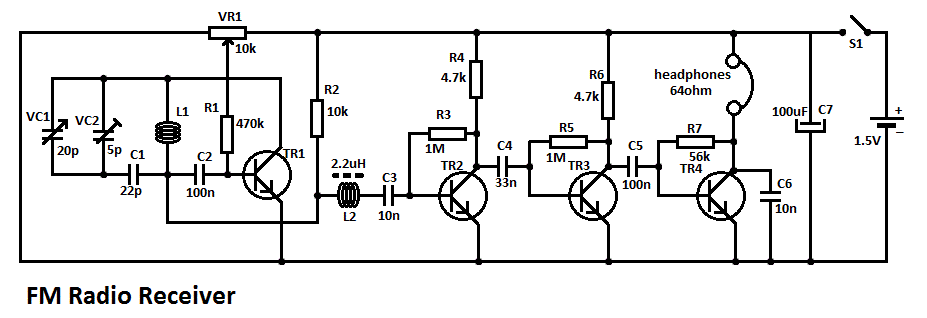
This simple FM radio receiver circuit consists of a regenerative RF stage, TR1, followed by a two or three-stage audio amplifier comprising TR2 to TR4. In some areas... This circuit is designed to receive FM radio signals, utilizing a regenerative...
A NE555 integrated circuit (IC) is utilized for the design of a variable low-frequency oscillator, and a schematic is provided. The NE555 timer IC is a versatile and widely used device in various electronic applications, particularly in generating precise timing...
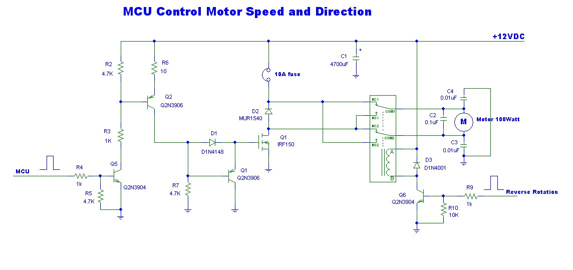
This is a power motor controller circuit designed for 12V applications. It utilizes a microcontroller unit (MCU) for signal control, operating at a high voltage level of approximately 3V. The circuit allows for the motor to be controlled to...
Warning: include(partials/cookie-banner.php): Failed to open stream: Permission denied in /var/www/html/nextgr/view-circuit.php on line 713
Warning: include(): Failed opening 'partials/cookie-banner.php' for inclusion (include_path='.:/usr/share/php') in /var/www/html/nextgr/view-circuit.php on line 713