
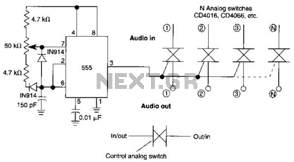
infa red remote control
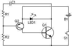
The described circuit involves a remote control system that utilizes an infrared (IR) LED to transmit a specific tone signal. The IR LED emits modulated light, which represents the tone. This modulation typically occurs at a frequency that is within the sensitivity range of the receiver's photodiode or phototransistor, allowing the receiver to distinguish the transmitted signal from ambient light sources.
In the transmitter circuit, the tone generation can be achieved using an oscillator circuit, which may include components such as a 555 timer IC or a microcontroller. The output of this oscillator is connected to the IR LED, which is driven by a current-limiting resistor to prevent excessive current flow. The modulation frequency is crucial as it ensures that the receiver can accurately detect the tone without interference from other light sources.
On the receiving end, the circuit is designed to include a photodiode or phototransistor that is sensitive to the wavelength emitted by the infrared LED. This component converts the received light signal back into an electrical signal. The output from the photodiode or phototransistor is then fed into a signal processing unit, which may consist of an amplifier and a demodulator. The demodulator extracts the tone from the signal, activating the output circuit only when the correct tone is detected.
The design ensures that the receiver remains inactive until it "hears" the specific tone, thereby minimizing the risk of accidental activations. This feature is particularly useful in applications where reliability and precision are paramount, such as remote-controlled devices in home automation or industrial settings.
Overall, the combination of the infrared transmission and the tone decoding mechanism enhances the functionality and reliability of the remote control system.his remote transmits a tone using an infa-red LED. This tone is decoded by the receiver. Since the receiver only switches when it ""hears"" the tone, there are no accidental activations.. 🔗 External reference
Related Circuits
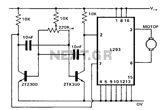
The control of both direction and proportional motor speed is accomplished through the rotation of a single potentiometer. The motor driver utilized is the SGS integrated circuit L293, which can drive up to 1 amp in either direction, depending...

A constant speed motor control can be achieved using closed-loop (servo) control. A constant speed motor maintains a steady speed regardless of variations in load. In a closed-loop control system, feedback is utilized to compare the actual speed of the...
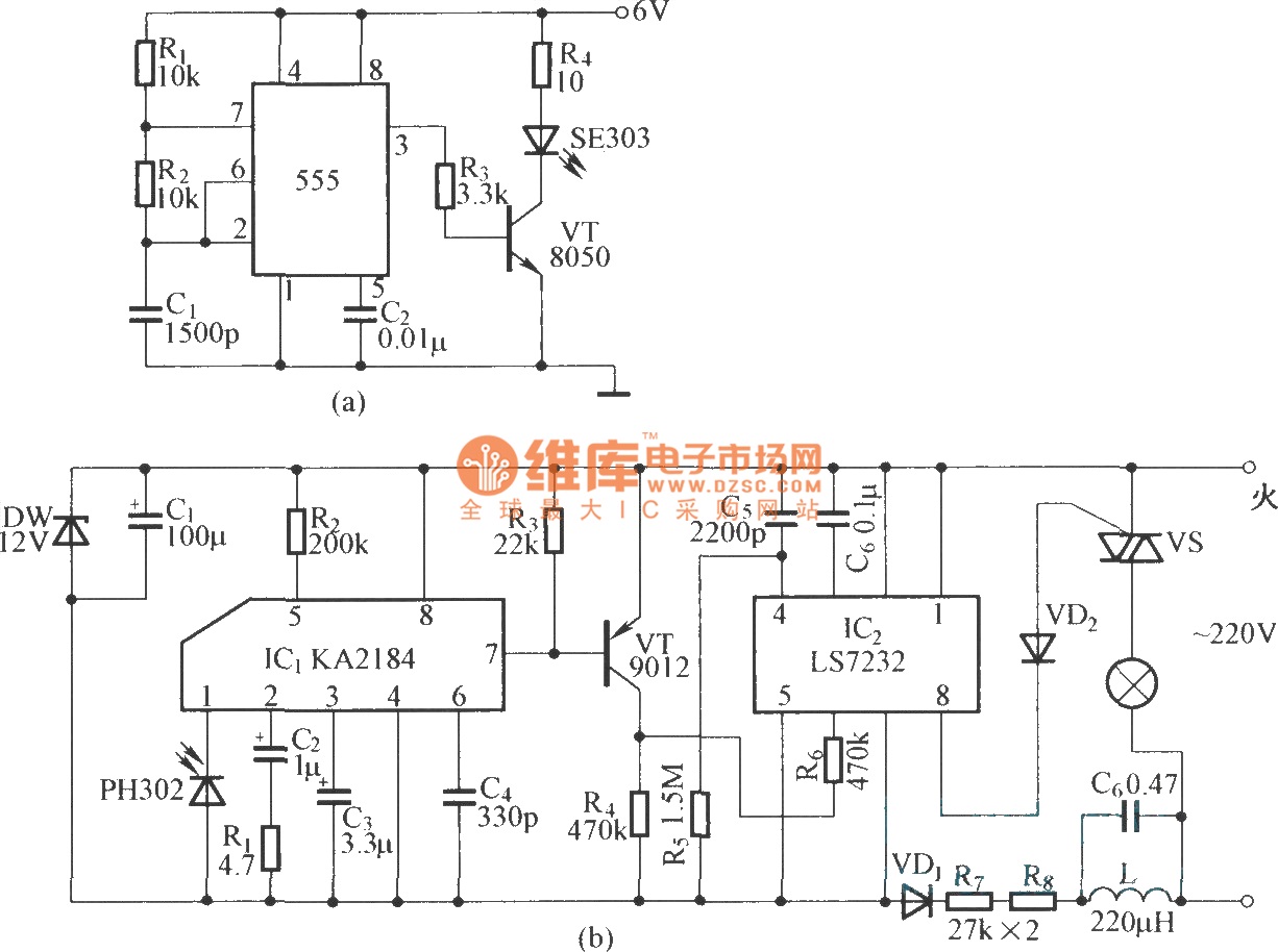
This is an infrared emission circuit diagram. The NE555 circuit generates a 40 kHz pulse, which is sent by the infrared emission control SE303 after being amplified by VT. The remote receiver and infrared dimming circuit are composed of...
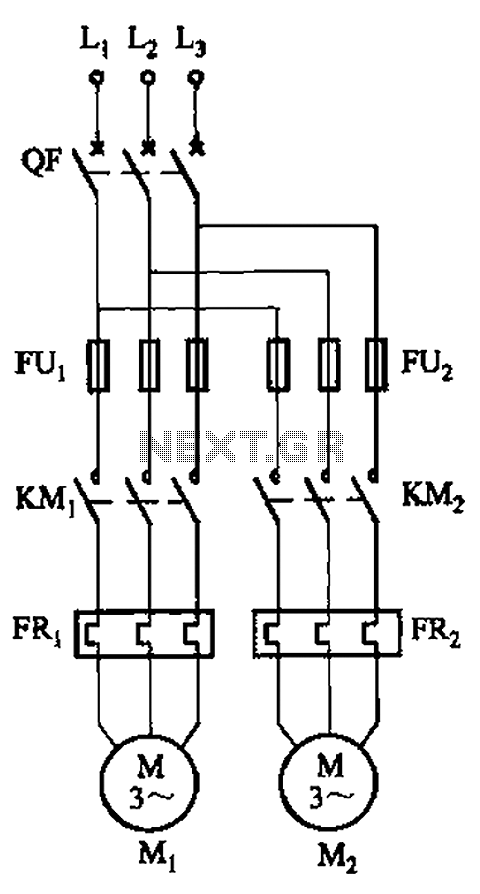
The circuit illustrated in Figure 3-64 operates with switch SA1 in the work position and switch SA2 in the standby position, allowing motor Mi to run while motor Mz remains on standby. In the event of downtime for motor...
A 555 timer can be configured to simulate a multi-gang potentiometer by controlling the mark-space ratio. The switching rate should be at least twice the maximum expected signal frequency that the potentiometer has to handle. The 555 timer is an...
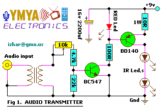
This project allows for wireless transmission of audio from a television to headphones using infrared (IR) technology. It eliminates the need for physical connections between the TV and the headphones. Instead of traditional wiring, it employs infrared light to...