
Infra-red Light Barrier Using 555
The short-range light barrier operates by utilizing a transmitter and a receiver configuration. The transmitter employs a 555 timer IC configured in astable mode to generate a continuous square wave signal at a frequency of around 4.5 kHz. This frequency is chosen to ensure effective modulation of the infrared (IR) light emitted by an IR LED, which serves as the light source for the barrier.
In the receiver unit, a photodiode or phototransistor detects the modulated IR light. The receiver is designed to be sensitive to the specific frequency emitted by the transmitter, allowing it to distinguish the signal from ambient light interference. When an intruder interrupts the beam of light between the transmitter and receiver, the modulation is disrupted, signaling the alarm system.
The circuit can be powered by a standard DC power supply, typically ranging from 5V to 15V, depending on the specific components used. Additional circuitry may be implemented to amplify the output signal from the receiver, which can then be connected to an alarm system or an LED indicator to alert users of the intrusion.
For optimal performance, the placement of the transmitter and receiver should be carefully considered to ensure a clear line of sight and to minimize the likelihood of false alarms caused by environmental factors. Adjustments to the sensitivity of the receiver may also be necessary to tailor the system's response to specific installation conditions.This is a short-range light barrier for use as an intruder alarm in doorposts, etc. The 555 in the transmitter (Figure 1) oscillates at about 4.5 kHz, sup.. 🔗 External reference
Related Circuits
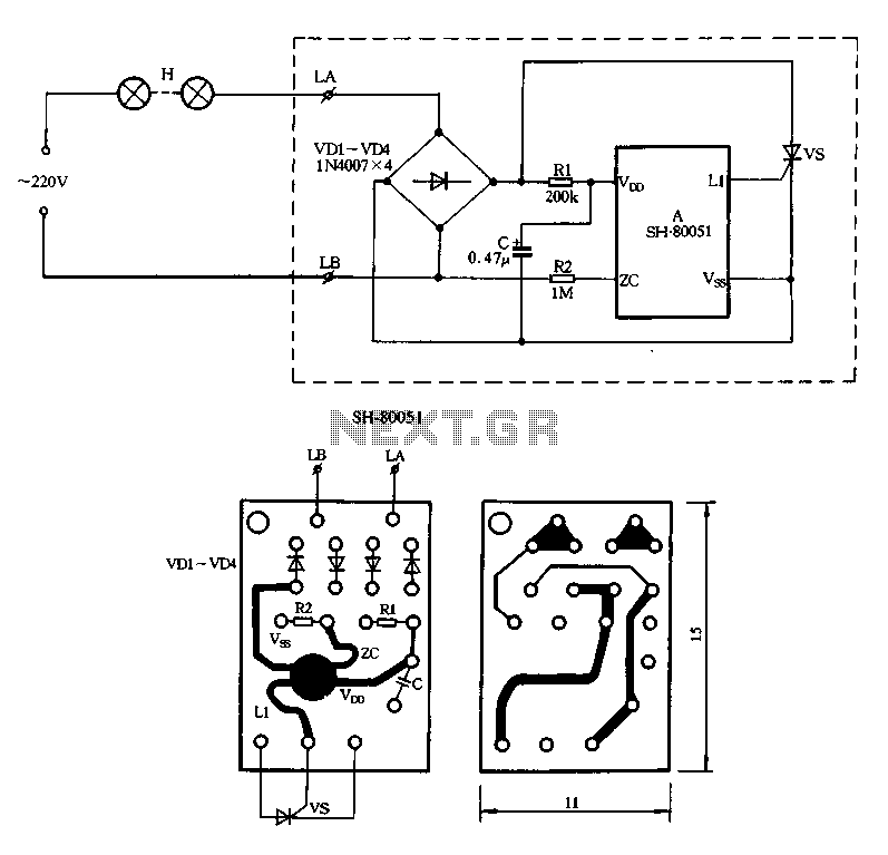
Figure 2-85 illustrates a single-channel SH-80051 flash controller. The SH-80051 chip features four terminals: the positive power supply terminal (VDD), the synchronization input (zc), the negative power supply terminal (VSS), and the drive output (L1). The chip operates with...

Most PN-junction diodes can be utilized as photodiodes. Although they are not specifically optimized for this purpose, they are functional. When reverse biased, a diode generates a small photovoltaic output that increases with light intensity. Light Emitting Diodes (LEDs)...
A line follower robot, abbreviated as LFR, is an autonomous robot designed to optically follow a line drawn on the floor. This involves the robot moving along an arbitrary line using a component known as a line sensor. A...

This article outlines a proposed solution for a 200 W power supply utilizing the FSFR2100 Fairchild Power Switch (FPS). The input voltage range is 90 to 265 VRMS, and it features six outputs. The 200 W power supply circuit based...
A 6-watt audio amplifier circuit utilizing the TDA2613 integrated circuit is presented. The TDA2613, produced by Philips Semiconductors, is a high-fidelity audio amplifier IC. This component is designed to be click-proof when switched on or off, resistant to short...
A battery-powered light control circuit is designed to delay the lighting of a small lamp during sudden power outages or nighttime situations when a blown fuse leaves a room in darkness. This circuit addresses the difficulty of locating matches...