
SH-80051 holiday lights ASIC
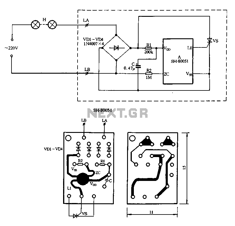
The SH-80051 flash controller is designed for decorative lighting applications, particularly for use in holiday lights and similar products. The circuit's primary function is to control the flashing of light strings by regulating the conduction angle of a silicon-controlled rectifier (SCR), which allows for precise control of the light output.
The power supply section of the circuit includes a 220V AC input, which is connected to the L and LB terminals of the chip. Resistor R1 serves as a current-limiting component, ensuring that the voltage and current levels are appropriate for the subsequent rectification stage. The rectification is performed by diodes VD1 to VD4, which convert the AC voltage to a pulsating DC voltage suitable for the chip's operation.
The VDD and VSS terminals are connected to a filtering capacitor, which smooths out any voltage fluctuations, providing a stable power supply to the chip. This stability is crucial for the reliable operation of the flashing patterns. Resistor R2 is used to generate an AC synchronous signal that is essential for timing the flash sequences.
The output from terminal L1 triggers the SCR, which is responsible for turning the light strings on and off. By adjusting the conduction angle of the SCR, the brightness and flashing frequency of the lights can be varied. This feature allows for various visual effects, making the lighting more dynamic and appealing.
The SH-80051 chip is programmed with six distinct flashing patterns, which can be selected and cycled through automatically. Each pattern offers a unique lighting effect, enhancing the aesthetic appeal of the light display. The patterns include rapid flashing, slow fading, and twinkling effects, which can be used to create different moods and atmospheres.
Overall, the SH-80051 circuit is a versatile and effective solution for controlling decorative lighting, providing users with a range of customizable options for their lighting displays.Figure 2-85 is a single road SH-80051 produced flash string, SH-80051 chip only four ports: positive power supply terminal VDD; synchronization input zc; negative power supply terminal vss; drive output Ll. 220V AC by light strings H input to terminal L and LB, by the well-limiting by Rl down after VDI-VD4 rectification, VDD and vss end C filter was added to the chip, R2 provides AC synchronous signal chip, Lt on output trigger pulse to change change vs SCR conduction angle, so as to achieve the purpose of string lights flashing H. SH-80051 There are six blinking patterns function, can automatically flip cycle. Six kinds of patterns specifically: 1, flashes A: 2, flashes B; 3, slowly fades A; 4, the stars blinking A; 5, slowly fades B; 6, stars twinkling B.
Related Circuits
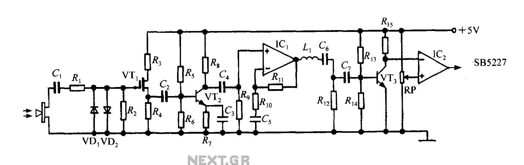
The SB5227 ultrasonic signal output is very weak and must be amplified via a power amplifier for effective transmission. A typical transmission circuit is illustrated in the accompanying figure. The SB5227 ultrasonic signal is sourced from output pin 10,...
Automatic color holiday lights circuit The automatic color holiday lights circuit is designed to control the operation of decorative lights during festive seasons. This circuit typically utilizes a microcontroller or a timer to manage the sequencing and color changes...
Most cars do not have delayed interior lights. The circuit presented can rectify this issue by gradually switching the interior lights of a car on and off. This feature facilitates tasks such as locating the ignition keyhole after the...

R4 prevents the output voltage from drifting toward one of the supply rails of the operational amplifier. It is understood that R4 should have a high resistance, although the reason for this is unclear. The schematic appears to be...
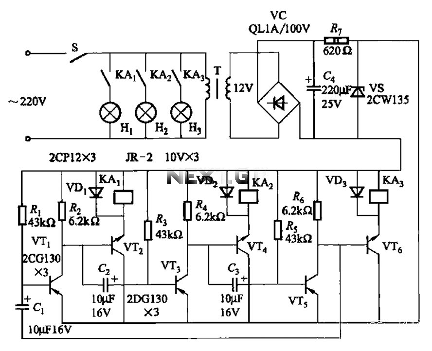
The transistors VTi, VT3, and VTs, along with the RC components, form three distinct multi-resonator oscillators. The oscillation frequency levels are dependent on the values of Ri, R3, Rs, and Cl, as well as Cz and C3s. The circuit comprises...
The CD4001 quad 2-input NOR gate is a highly versatile integrated circuit (IC) that can be utilized in numerous applications. This example demonstrates its use in a simple alarm system. The recommended power supply voltage for the CD4001 ranges...