
Infra Red Switch remote control
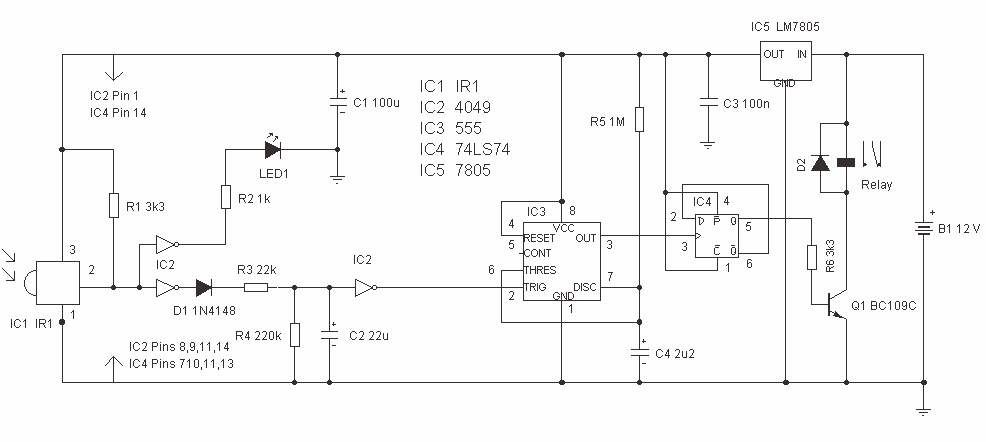
The described circuit functions as a universal switch that can be controlled via any standard Infrared (IR) remote control operating within the frequency range of 36-38 kHz. The primary component of this system is a relay that serves to switch an external load on or off based on the received IR signals. The operation is initiated by pressing any button on the remote control for a duration of approximately 1.5 seconds, a timing determined by the resistor R3 and capacitor C2 in the circuit.
Once activated, the relay latches in the 'on' position, maintaining the state until a reset command is received. The reset is accomplished by pressing and holding any button on the remote control for a brief period, which allows the circuit to return to its initial state.
The IR receiver in the circuit detects the modulated signals from the remote control. However, these signals often contain jagged edges due to the nature of the modulated IR data. To ensure reliable operation, these jagged edges need to be smoothed out. This is achieved through the use of a 555 timer configured in monostable mode (IC3). The monostable configuration allows the circuit to generate a clean, stable output pulse of a specific duration whenever it receives an appropriate trigger signal from the IR receiver.
The output duration of the 555 timer can be adjusted based on the component values selected for R3 and C2, ensuring that the timing is optimal for the relay operation. This design allows for flexibility in the choice of remote control buttons, enabling the universal switch to be tailored to various applications while ensuring reliable and consistent performance.This is a single channel (on / off) universal switch that may be used with any Infra Red remote control using 36-38kHz. (This is a very common remote handset frequency). Any "button" of any remote control may be used to work this universal switch. The button must be pressed for about one and a half seconds (determined by R3 and C2) before the relay will operate.
The circuit will remain in this state (latched) until reset. To reset, any button is pressed on the remote handset and held for a short duration. The pulses are further buffered and contain "jaggered edges" as shown above. These edges are produced by the modulated IR data, and have to be removed. This is achieved using a 555 timer wired as a monostable, IC3, having an output pulse duratio 🔗 External reference
Related Circuits
As circuit power supply voltages decrease and green energy trends gain popularity, designers should re-evaluate circuits that continuously consume power to reduce overall system power consumption. One such circuit is the "normally-ON" circuit, which can now be redesigned with...
If the unit has been idle for an extended period due to depleted AAA batteries, resulting in a malfunctioning display or inoperability, the most likely requirement is the replacement of the internal lithium battery. Although the unit was advanced...
It is necessary to adjust the 10K potentiometer while aiming the device at the television to obstruct the infrared rays from the remote control. This adjustment can be achieved through a process of trial and error. The circuit in question...
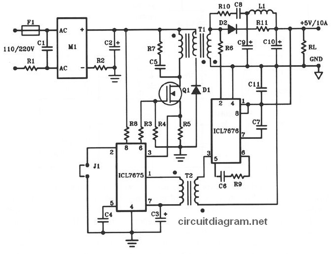
The following diagram illustrates the design of a 50W offline switching power supply circuit. This circuit is powered by a MOSFET, specifically the BUZ80A/IXTP4N8 for 220V AC input and the GE IRF823 for 110V AC input voltage. The output...
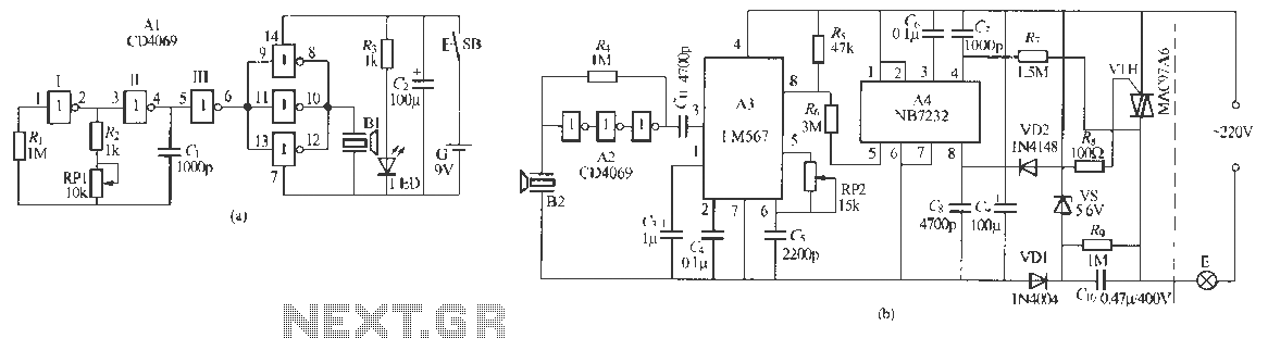
Remote control dimmer lights consist of two parts: an ultrasonic transmitter and an ultrasonic remote control dimmer receiver. The ultrasonic wave transmitter circuit is detailed in A 229 (a). It includes components such as R, R., RP1, and C,...
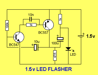
This is a simple 1.5V powered LED flasher circuit diagram. This circuit can flash 1.7V or 2.3V LEDs (depending on the color) using a 1.5V DC input. The LED will turn on when the 100µF capacitor is charged by...
Warning: include(partials/cookie-banner.php): Failed to open stream: Permission denied in /var/www/html/nextgr/view-circuit.php on line 713
Warning: include(): Failed opening 'partials/cookie-banner.php' for inclusion (include_path='.:/usr/share/php') in /var/www/html/nextgr/view-circuit.php on line 713