
Circuit 22W Stereo Amplifier Using TDA1554
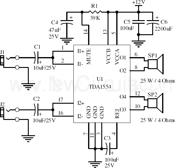
The 22-watt stereo audio power amplifier circuit based on the TDA1554 is an efficient solution for audio amplification in various applications, including home audio systems and portable speakers. The TDA1554 is a dual power amplifier capable of delivering high-quality audio output while maintaining thermal stability.
The circuit configuration includes essential components such as capacitors for filtering, resistors for setting gain and stability, and the TDA1554 IC itself. The power supply is a critical aspect, requiring a stable 12V source that can provide sufficient current, particularly at peak audio levels. The use of a heatsink is crucial to manage the thermal output of the amplifier, as the device can generate significant heat during operation.
In addition to R1, other passive components in the circuit play vital roles in ensuring optimal performance. Capacitors are typically employed in the power supply section to smooth out voltage fluctuations, while coupling capacitors may be used at the input and output stages to block DC offsets and allow only AC audio signals to pass.
The layout of the circuit should be designed to minimize noise and interference, with careful attention paid to the placement of components and the routing of traces. Grounding practices are also important to ensure that the amplifier operates without hum or buzz, which can degrade audio quality.
Overall, this amplifier circuit represents a straightforward yet effective approach to stereo audio amplification, leveraging the capabilities of the TDA1554 to deliver robust performance in a compact form factor.Here is the 22 watt stereo audio power amplifier circuit diagram based on TDA1554 and integrated circuit from NXP semiconductors (formerly PHILIPS semiconductors). It is very simple and useful circuit for amplify the stereo signals. The circuit dissipates roughly 28 watts of heat, so a good heatsink is necessary. The chip should run cool enough to touch with the proper heatsink installed. the circuit operates at 12 Volts at about 5 Amps at full volume. Lower volumes use less current, and therefore produce less heat. R1 is also a 5% resistor. 🔗 External reference
Related Circuits
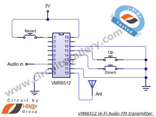
This article provides the circuit schematics for an FM transmitter along with the necessary explanations. The primary component utilized is the VMR6512 IC, a highly integrated FM audio signal transmitter chip designed for Hi-Fi audio applications. This chip can...
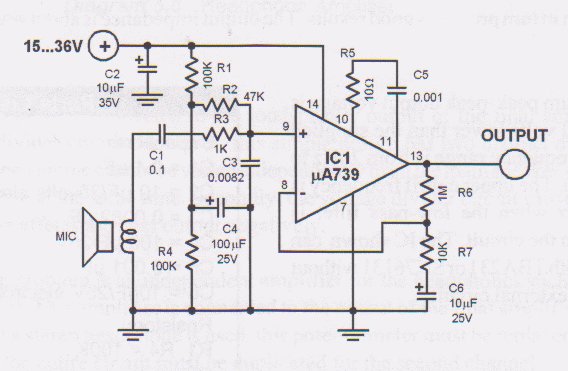
This circuit is a low voltage microphone preamplifier that operates with a 1.5V power supply. It features a reference with a 500 kHz unity-gain bandwidth, functioning as a preamplifier with a gain of 100. The output from this stage...
The Olimex P-40 development board will be utilized, though the circuit can also be constructed on a breadboard due to its simplicity. The schematic for the initial implementation of servo control is provided below. Servos, like any motors, can...
This metal detector schematic circuit is based on a transistor radio as a detector. This metal detector is entirely different from other metal detectors because this circuit does not have a speaker. With the radio tuned to a weak...
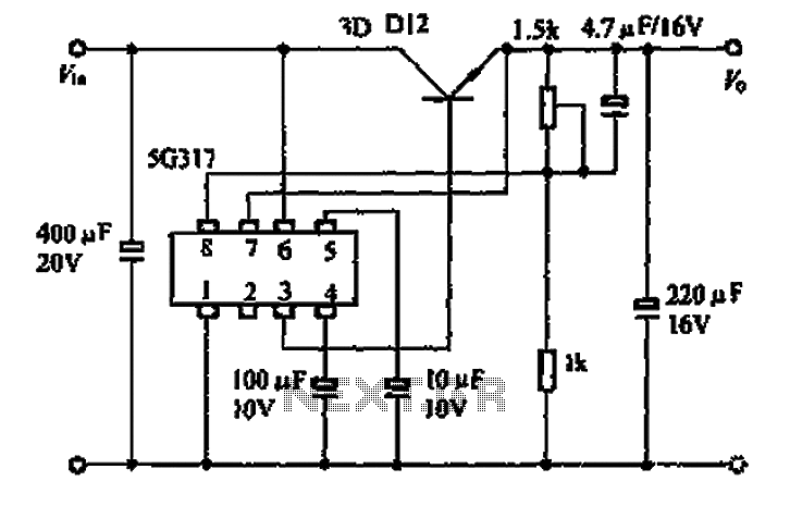
The 5G317 is an integrated voltage regulator circuit used in wiring applications for televisions. The maximum input voltage for the 5G317 should be less than 25V, while the output voltage ranges from 10V to 18V. The maximum output current,...
A pH meter is a precise voltmeter that measures the generated voltage of pH electrodes. The demand for such a meter is significant. A pH meter operates by utilizing a combination of a glass electrode and a reference electrode. The...
Warning: include(partials/cookie-banner.php): Failed to open stream: Permission denied in /var/www/html/nextgr/view-circuit.php on line 713
Warning: include(): Failed opening 'partials/cookie-banner.php' for inclusion (include_path='.:/usr/share/php') in /var/www/html/nextgr/view-circuit.php on line 713