
infrared remote for toy car motor
The remote control circuit for battery-operated toy cars employs a straightforward design that effectively utilizes infrared communication for operation. The system is powered by a 6V battery, which energizes the CD4017 decade counter, configured to function as a toggle flip-flop, allowing for the control of the toy car's motor. The power-on-reset mechanism, consisting of capacitor C3 and resistor R6, ensures that the circuit initializes correctly upon being powered.
The inclusion of LED1 serves as a visual indicator of the circuit's standby condition, providing immediate feedback to the user regarding the operational status. The integrated infrared receiver/demodulator, either the SFH505A or TSOP1738, plays a critical role in interpreting signals from the remote control. The high output level during standby indicates that the circuit is ready to receive commands, while the reverse bias state of transistor T1 prevents any unintended activation of the motor.
Upon pressing a button on the remote, the IR receiver's output momentarily drops to a low state, activating transistor T1. This triggers the monostable circuit, which generates a pulse that clocks the CD4017, allowing the motor driver transistor T2 to engage and power the motor for movement. The design incorporates a current-limiting resistor (R8) to protect the motor and ensure reliable operation during startup.
The circuit's robustness against ambient light interference is a significant advantage, making it suitable for various environments. However, precautions must be taken regarding specific types of lighting, such as fluorescent lamps, which may introduce noise in the infrared signals. The assembly process is straightforward, with clear instructions for wiring and placement of components, facilitating easy integration into toy cars. This design exemplifies a practical application of electronic components in consumer products, enhancing user interaction through remote control technology.This add-on circuit enables remote switching on/off of battery-operated toy cars with the help of a TV/video remote control handset operating at 30 40 kHz. When the circuit is energised from a 6V battery, the decade counter CD4017 (IC2), which is configured as a toggle flip-flop, is immediately reset by the power-on-reset combination of capacito
r C3 and resistor R6. LED1 connected to pin 3 (Q0) of IC2 via resistor R5 glows to indicate the standby condition. In standby condition, data output pin of the integrated infrared receiver/demodulator (SFH505A or TSOP1738) is at a high level (about 5 volts) and transistor T1 is off` (reverse biased). The monostable wired around IC1 is inactive in this condition. When any key on the remote control handset is depressed, the output of the IR receiver momentarily transits through low state and transistor T1 conducts.
As a result, the monostable is triggered and a short pulse is applied to the clock input (pin 14) of IC2, which takes Q1 output (pin 2) of IC2 high to switch on motor driver transistor T2 via base bias resistor R7 and the motor starts rotating continuously (car starts running). Resistor R8 limits the starting current. When any key on the handset is depressed again, the monostable is retriggered to reset decade counter IC2 and the motor is switched off.
Standby LED1 glows again. This circuit can be easily fabricated on a general-purpose printed board. After construction, enclose it inside the toy car and connect the supply wires to the battery of the toy car with right polarity. Rewire the DC motor connections and fix the IR receiver module in a suitable location, for example, behind the front glass, and connect its wires to the circuit board using a short 3-core ribbon cable/shielded wire.
Note. Since the circuit uses modulated infrared beam for control function, ambient light reflections will not affect the circuit operation. However, fluorescent tubelights with electronic ballasts and CFL lamps may cause malfunctioning of the circuit.
🔗 External reference
Related Circuits
This section describes an experimental low power, low bandwidth data signaling system that was initially made to operate at 55 MHz (television channel 2 in the U.S.). Before operating a radio transmitter, find out what kind of transmitter operation,...
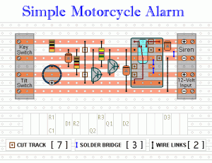
The following circuit is a simple, inexpensive, and easy-to-build motorcycle alarm. The circuit requires only two transistors to drive a relay, which acts as a switch to activate a buzzer. Any number of normally-open switches can be used. Mercury...
All distances mentioned can vary depending on the infrared transmitting and receiving LEDs used and are significantly affected by the color of the reflecting surface. Black surfaces greatly reduce the device's sensitivity. This circuit can also be applied in...
This is an infrared (IR) proximity detector circuit. A matched infrared emitter and detector pair is used in this circuit. The voltage-controlled oscillator is involved. The infrared proximity detector circuit utilizes a matched pair of infrared emitter and detector components...

A GC Electronics P/N J4-815 transducer is utilized to receive 40-kHz acoustic remote-control signals. The receiver activates a relay to control another circuit. The GC Electronics P/N J4-815 transducer is designed specifically for the reception of 40-kHz acoustic signals, which...
A car battery deteriorates in use, and its life seldom exceeds four years. When new, its voltage may drop to only 2V while cranking the engine. A car battery, typically a lead-acid type, is essential for providing the necessary electrical...
Warning: include(partials/cookie-banner.php): Failed to open stream: Permission denied in /var/www/html/nextgr/view-circuit.php on line 713
Warning: include(): Failed opening 'partials/cookie-banner.php' for inclusion (include_path='.:/usr/share/php') in /var/www/html/nextgr/view-circuit.php on line 713