
PC Infrared Receiver
Parts list
R1 3.3K 1/4W
R2 10K 1/4W
R3 100K 1/4W
R4 10K 1/4W
R5 100K 1/4W
R6 220 1/4W
D1 1N4148
D2 LED 3mm
C1 4.7uF/16V Electrolytic
Q1 BC548
Q2 BC558
IC1 78L05
IC2 TSOP 1736/38/40 (may work with Siemens SFH506xx receivers also)
E1 CR2032 3V battery + PCB base
Misc Three pins to connect the serial cable (optional)
The improvements of this project compared to the ones already published on the internet are that it uses regulated power for the infrared receiver module (TSOP 17xx), has improved sensitivity (worked at a distance of about 10 m), and features a status LED which is powered by an external battery source and is driven by two transistors. Upon signal reception, the LED blinks to provide visual feedback to the sender. The Girder software for this project was preferred because it is freeware, stable, customizable, features a large number of commands, and supports user plugins. It is a bit difficult to learn at first, but after a while, it deploys a great number of possibilities that other programs (even commercial ones) lack. Nevertheless, with the right corrections (pin changes), this project may be used with other software (WinLIRC, IRAssistant, Miriam, PCRemote), but no such testing has been carried out yet. This is maybe a good point for further search. The PCB features narrow tracks (16 mil) so special care should be paid during the construction. The 4.7 uF capacitor is bent towards the board in order to save height if the circuit is to be placed in a small plastic box.
The circuit operates by receiving infrared signals from a remote control, which are processed by the TSOP infrared receiver module (IC2). The output from the TSOP IC is fed into the base of transistor Q1 (BC548), which acts as a signal amplifier. The amplified signal is then used to drive transistor Q2 (BC558), which controls the status LED (D2) and indicates successful signal reception. The status LED provides immediate visual feedback, enhancing user interaction. The regulated power supply from IC1 (78L05) ensures that the circuit operates reliably, even with variations in the input voltage from the battery (E1). The choice of resistors (R1 to R6) is critical for setting the appropriate biasing and gain for the transistors, ensuring optimal performance of the infrared receiver. The inclusion of a 4.7 uF capacitor (C1) helps to stabilize the power supply and filter out noise, further improving the reliability of the circuit. Overall, this design represents a compact and effective solution for remote control applications, leveraging both hardware and software capabilities for enhanced usability.This is the latest version of the Improved Infrared Receiver with Status LED which can control any desktop PC with an ordinary remote control. The project comes along with a small PCB in order to save space. It connects to the serial port as stated in the schematic and uses the freeware Girder (www.girder.nl) software together with Igor?s Plugin (www.cesko.host.sk/girderplugin.htm) to send commands to the PC.
The potential uses of this device are countless (control MP3 players, CD and DVD players, radio and TV cards, even move the mouse cursor and shutdown the computer remotely !). Again, note that any ordinary remote control can be used by training Girder to learn its signals. Parts list R1 3.3K 1/4W R2 10K 1/4W R3 100K 1/4W R4 10K 1/4W R5 100K 1/4W R6 220 1/4W D1 1N4148 D2 LED 3mm C1 4.7uF/16V Electrolytic Q1 BC548 Q2 BC558 IC1 78L05 IC2 TSOP 1736/38/40 (may work with Siemens SFH506xx receivers also) E1 CR2032 3V battery + PCB base Misc Three pins to connect the serial cable (optional) The improvements of this project compared to the ones already published in the internet is that it uses regulated power for the infrared receiver module (TSOP 17xx), has improved sensitivity (worked at a distance of about 10 m), and features a status led which is powered by an external battery source and is driven by two transistors. Upon signal reception, the led blinks to provide a visual feedback to the sender. The Girder software for this project was preferred because it is first of all freeware, it is stable and customizable, features a large number of commands and supports user plugins.
It is a bit difficult to learn at first, but after a while it deploys a great number of possibilities that other programs (even commercial ones) lack. Nevertheless, with the right corrections (pin changes) this project may be used with other software (WinLIRC, IRAssistant, Miriam, PCRemote) but no such testing has been carried out yet.
This is maybe a good point for further search. The PCB features narrow tracks (16 mil) so special care should be paid during the construction. The 4.7 uF capacitor is bent towards the board in order to save height if the circuit is to be placed in a small plastic box. 🔗 External reference
Related Circuits
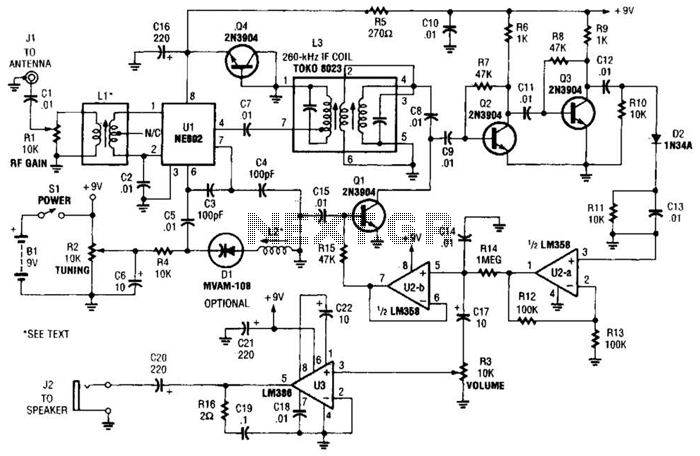
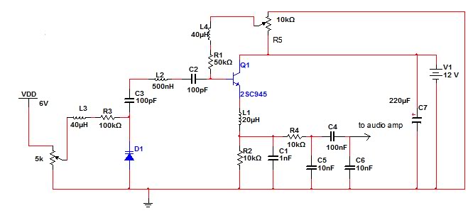
The integrated circuit Ul (an NE602 double-balanced mixer) functions as both an oscillator and a frequency mixer. Signals from the antenna input (at Jl) are transmitted through a DC-blocking capacitor C1 to the RF gain control, Rl, and subsequently...
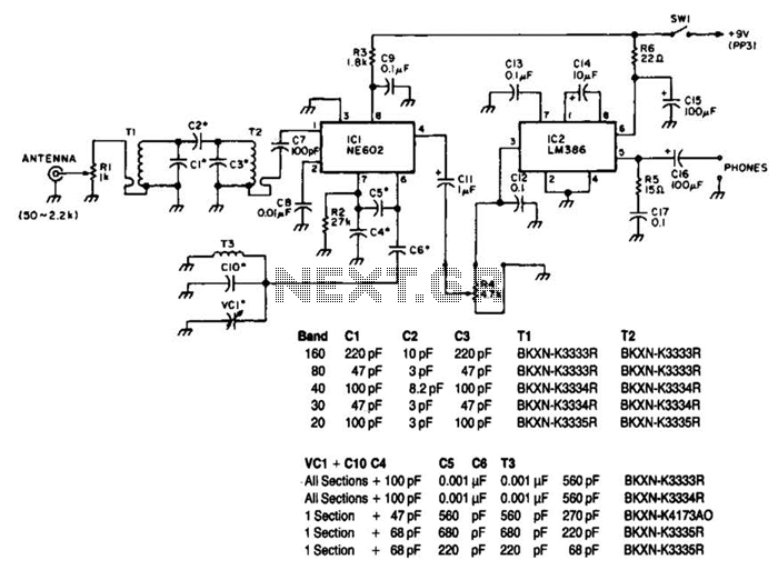
Note that T1 and T2 are TOKO components, including part numbers for the coils T1 and T2. The direct-conversion receiver shown utilizes a double-tuned input network made from readily available TOKO coils. IC1, an NE602, serves as a voltage-controlled...
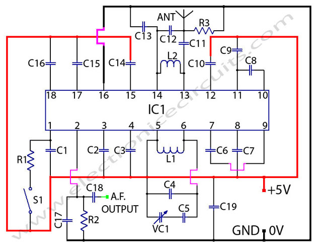
The TDA7000 is a monolithic integrated circuit designed for mono FM portable radios or receivers, emphasizing minimal peripheral components for compact size and cost-effectiveness. This integrated circuit features a Frequency-Locked-Loop (FLL) system with an intermediate frequency of 70 kHz....
The circuit described is an FM receiver. When a 9V power supply is used, the circuit exhibits good performance. However, performance issues arise when an AC/DC rectifier or switch-mode power supply is utilized. The FM receiver circuit operates by demodulating...
An AM receiver depends on the original carrier signal (station frequency) being amplitude modulated, meaning the original amplitude (strength) varies at an audio rate. Figure 1 illustrates an unmodulated carrier signal as it might appear on an oscilloscope, showing...
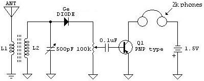
The following schematic illustrates a Crystal Radio Receiver Circuit Diagram that incorporates audio frequency (AF) amplification utilizing a Germanium transistor. The inclusion of AF amplification enhances the audio output quality. The Crystal Radio Receiver Circuit is a simple yet effective...