
Infrared-Led based Wireless Data & Voice Communication withCircuit

The electronic infrared communication system circuit is designed to facilitate efficient transmission and reception of signals over short distances using infrared light. The condenser microphone acts as the initial input transducer, converting acoustic signals into corresponding electrical signals. These signals are weak and require amplification for effective processing.
The operational amplifier IC-741 is configured in an inverting mode, which allows for signal inversion and amplification. The gain of the amplifier can be adjusted by changing the resistance values in the feedback loop, specifically through the use of a variable resistor (1M ohm recommended). This flexibility enables optimization of the circuit for different sound input levels and distances.
Following the initial amplification stage, the output signal is fed into a push-pull amplifier configuration using transistors BC548 and BC558. This configuration enhances the output power, allowing the signal to drive infrared LEDs effectively. The feedback resistor R2, along with resistors R1 and R8, ensures stability and proper functioning of the operational amplifier, while capacitors C1 and C3 help in filtering and smoothing the output signal.
The connection of pin 2 of the IC to the variable resistor (VR1) allows for fine-tuning of the amplifier's response, enabling users to cater to specific application requirements. The entire circuit operates on a 6-volt DC power supply, which is suitable for low-power applications and ensures safe operation of the components involved.
Overall, this circuit serves as a foundational model for developing an infrared communication system, with potential applications in remote control devices, wireless audio transmission, and other communication technologies that utilize infrared signals.Objective of this project are to Design a circuit of an electronic infrared communication system, develop new ideas to implement this circuit purposely, to study the circuitry and different types of components & DTMF generator, DTMF decoder, op-amp and infrared-LED in the circuit. The main part of Circuit is an amplifier. This sound signals (even at a distance of 2 meters from the mic) are picked up by the condenser microphone and converted into electrical variation, which are amplified by the op-amp. Operational amplifier IC- 741 is use in the inverting mode with a single supply using divider network of resistor the gain of IC can be set be varying the feed back through R5/6 resistance (can place a 1M variable) here the output of IC is further amplified buy the push-pull amplifier using transistor BC.
548/558 pair, in this circuit are R2 is feed back resistance with R1/8 and C1/3 to connected IC-741. The IC`s pin 2 is connect VR1 (variable resistance) through connect to O/P of T1 (transistor) also use 6volt DC. 🔗 External reference
Related Circuits
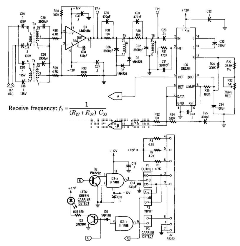
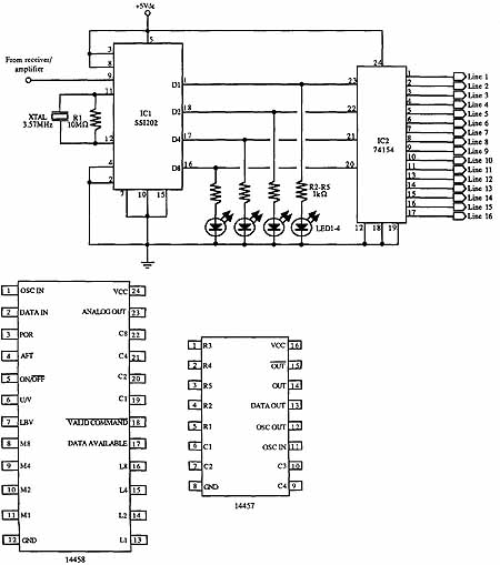
This receiver consists of an input network, amplifier IC7, FSK PLL detector IC8, and output amplifier/interface circuits Q2, Q3, IC3A, and IC3B, which include a 1488 Quad RS232 line driver for the carrier-current signal. The tuned amplifier IC7 amplifies...
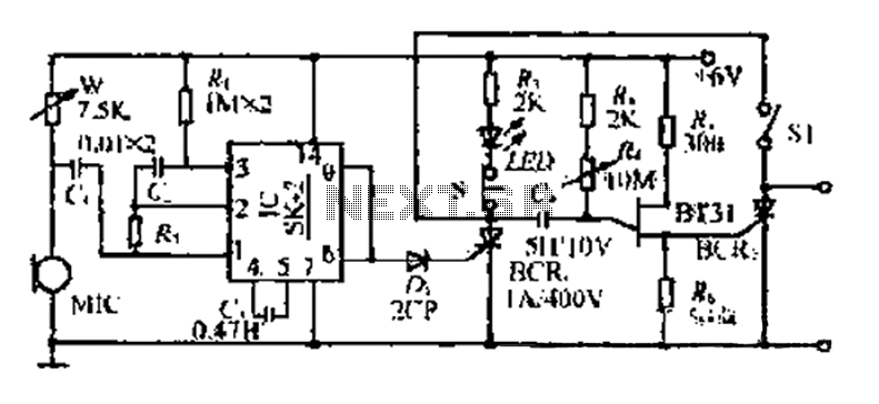
The circuit includes a microphone (MIC) housed in a cylindrical body that captures sound when an object makes contact. The audio signal is coupled to an integrated circuit (IC) for amplification. The output from the IC, at pins 6...
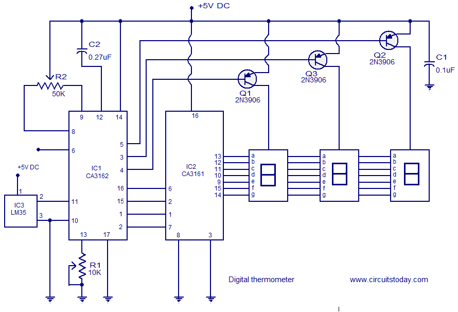
A simple digital thermometer circuit without a microcontroller and featuring a seven-segment LED readout is presented. The circuit utilizes three integrated circuits (ICs): CA3162, CA3161, and LM35. The CA3162 is a monolithic analog-to-digital (A/D) converter with a BCD output....
This circuit prioritizes a microphone and preamplifier (voice circuit) over any other audio signal, functioning similarly to a one-way intercom. When the push-to-talk switch is activated, the main amplifier switches from music to the voice signal. Essentially, a voice-over...
The previous section discussed several basic free-air laser light communication projects. It covered the modulation of a He-Ne laser beam using a transformer, transistor, and a piece of Mylar foil stretched in a needlepoint hoop. Various methods for electronically...
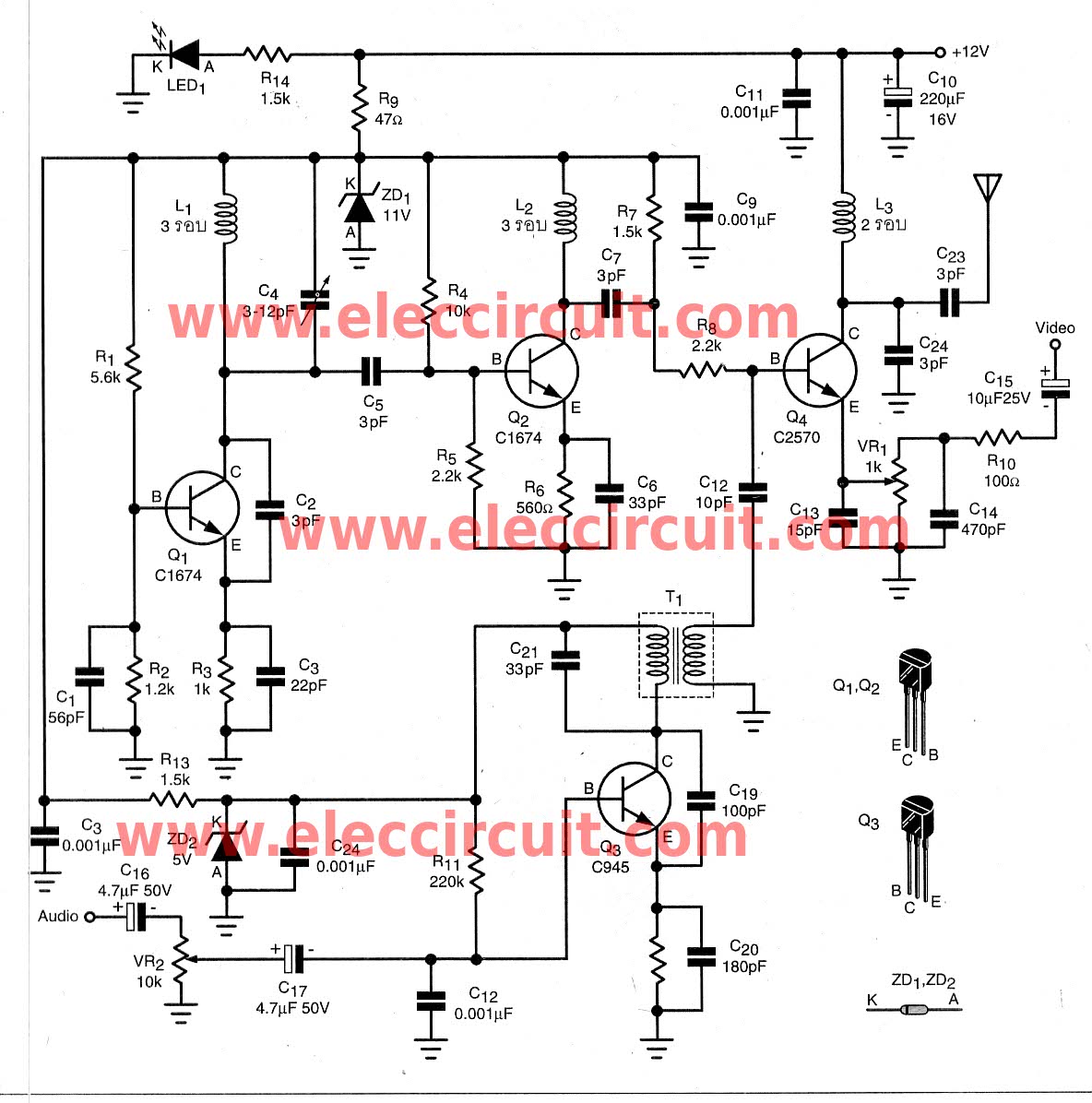
To transmit video and audio signals to multiple televisions simultaneously, a video amplifier splitter utilizing a transistor can be employed. A video amplifier splitter is an electronic device designed to distribute a single video and audio signal to multiple output...