
Audio Voice-Over Circuit
This circuit design effectively integrates a microphone and preamplifier to ensure that voice communication takes precedence over other audio signals. The use of a relay as a change-over switch is a practical choice, allowing seamless transition between music playback and voice communication without audible artifacts. The BC109C transistors serve as a robust solution for the preamplifier stage, ensuring high gain and low output impedance, which are critical for maintaining audio quality over extended cable runs.
The preamplifier is designed to work optimally with an Electret Condenser Microphone, which is known for its sensitivity and low noise characteristics. The inclusion of a 100uF capacitor and a 1k resistor at the output stage is a well-considered approach to eliminate any DC offset that could interfere with the audio signal, thus preventing unwanted noise during operation.
The LM380 amplifier provides sufficient power amplification for driving speakers in various environments. The configuration allows for easy adjustment of volume levels for both the music source and the voice input, ensuring that users can tailor the audio output to their preferences. The implementation of a normally closed contact for the audio input ensures that music playback is uninterrupted until the push-to-talk function is activated, allowing for effective communication without disrupting the listening experience.
Overall, this circuit is highly suitable for remote applications, providing a reliable and efficient means of communication while minimizing interference and maintaining audio fidelity.This is a circuit where a microphone and preamp circuit (voice circuit) have priority over any other audio signal. You can think of this as a one way intercom, if the main amplifier is used for listening to music, then when the push to talk switch is pressed, the amplifier is switched to the voice signal.
In its simplest form, a voice-over unit is just a microphone and change-over switch feeding an amplifier, the output from the microphone having priority over the amplifiers audio signal when the "push-to-talk" switch is pressed. In this circuit, a preamplifier immediately follows the microphone and is designed to be used some distance away from the main amplifier.
The changeover switch is nothing more than a relay with a single changeover contact. For completion, an amplifier based on the LM380 is shown. Three wires are needed to connect the remote microphone unit to the amplifier and switching unit. With reference to the above schematic, the two BC109C transistors are used to make a microphone preamplifier. The left hand BC109C operates in common emitter mode, the right hand emitter follower. The combination form a high gain, low output impedance amplifier, capable of driving a long audio cable.
Screened cable is not required as the output impedance from the microphone pre-amp is very low, and will be immune to mains hum and background noise. The input is shown as a three wire Electret Condenser Microphone though two wire ECM`s may also be used.
The output of the pre-amp is via a 100uF capacitor and 1k resistor. The 1k resistor here plays an important role, eliminating the dc component of the audio output. (See also eliminating the DC "thump" also on this web site. ) A cable of three or more wires is wired to the remote amplifier. The amplifier shown here is based on the National Semiconductor LM380. The input signal is passed via the normally closed contact of a changeover relay, the 10k potentiometer being the volume control for the audio input source. The 10k preset at the normally open contact allows volume control of the voice input, note that this signal has by-passed the normal volume control.
At the remote end, when the push-to-talk switch is pressed, the relay will operate and the "voice" signal will be heard in the speaker. There will be no "thump" or "thud" on voice-over as direct current has been eliminated as already mentioned.
A suitable application for this circuit would be for use in a remote location such as a workshop or shed. 🔗 External reference
Related Circuits
The amplifier is based on an integrated circuit TDA2822M. With this circuit, an amplifier can be built with up to 2 W. This much power circuit is able to supply only at peak times; continuous excitation would not be...
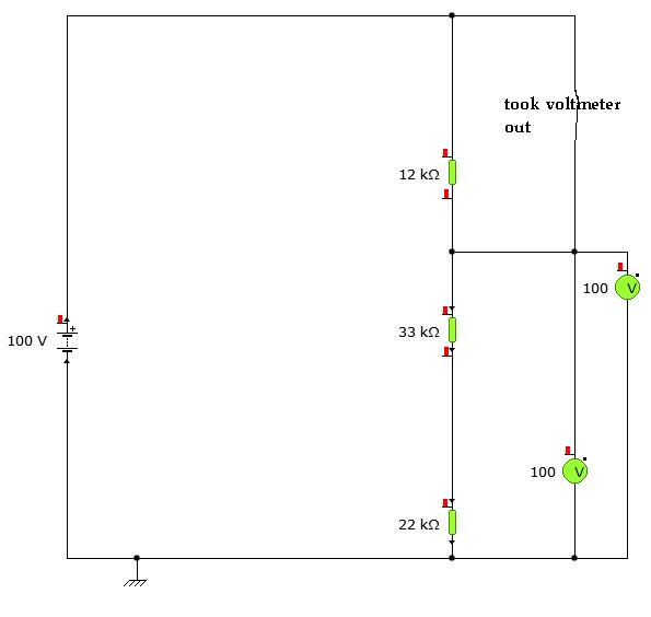
A user is utilizing YENKA software to diagram circuits but is experiencing confusion regarding the voltage calculations in a basic series circuit, as illustrated in the attached image. In a basic series circuit, components are connected end-to-end, forming a single...
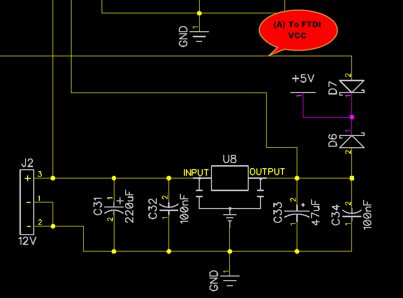
When only the voltage regulator (VR) supplies power to the circuit, the microcontroller unit (MCU) will receive power from the +5V bus, while the FTDI chip will only receive VCCIO. At the midpoint of the voltage divider formed by...
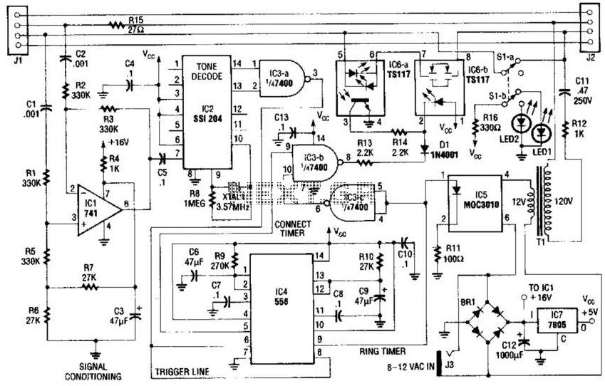
The fax mate separates the fax machine from the phone line, rings the fax machine on command, connects equipment to incoming lines, and senses the end of the message. When a touch tone pound signal (#) is detected, it...
This complete high quality, low noise 5-BAND GRAPHIC EQUALIZER circuit is based around Monolithic Linear integrated circuit LA3600 manufactured by SANYO. This circuit is very easy to build and has good Quality. You can use it with Portable component...
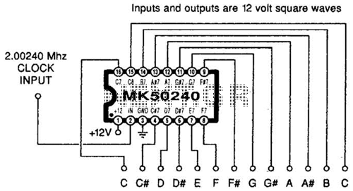
Using an MK50240, this circuit generates 12 top octave tones. The input and output lines can be separated using a binary divider IC to achieve the lower notes. Inputs and outputs are 12-volt square waves. The MK50240 is a specialized...
Warning: include(partials/cookie-banner.php): Failed to open stream: Permission denied in /var/www/html/nextgr/view-circuit.php on line 713
Warning: include(): Failed opening 'partials/cookie-banner.php' for inclusion (include_path='.:/usr/share/php') in /var/www/html/nextgr/view-circuit.php on line 713