
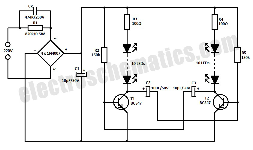
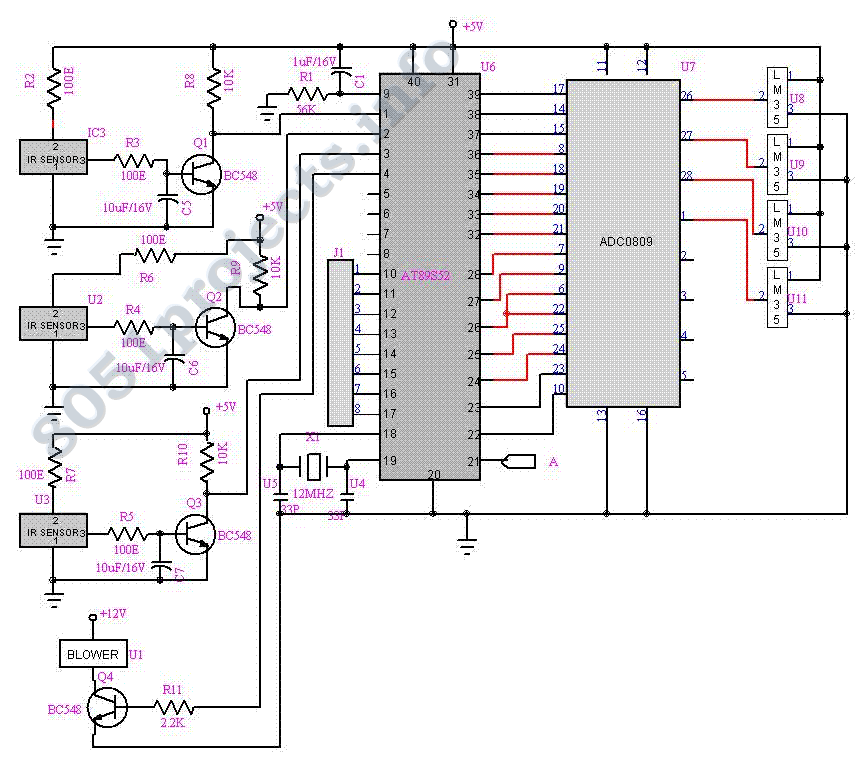
Infrared Model Train Detector Circuit

This infrared model train detector circuit provides a practical solution for enhancing model railway systems by enabling automatic detection of trains. The integration of the LM567 PLL Tone Decoder allows for reliable signal processing, ensuring that the system can accurately identify the presence of trains based on the reflected infrared light. The use of the CNY18-2 opto-coupler ensures electrical isolation between the detector circuit and any connected external systems, which can include alarms, automated signals, or other control mechanisms.
To optimize the performance of the circuit, careful attention should be paid to the positioning of the infrared components. D1 should be aligned to emit infrared light directly onto the track, while D2 must be positioned to receive only the light that is reflected back by the train wagons. This setup minimizes false triggering from ambient light sources and enhances the reliability of the detection system.
The choice of infrared emitters and detectors is crucial; they should be selected based on their wavelength compatibility to ensure efficient operation. Additionally, the tuning of resistor R2 is essential, as it influences the sensitivity of the detector. Depending on the reflective properties of the model train wagons, adjustments to R2 may be required to achieve the desired detection range and response time.
Overall, this circuit design is an excellent addition to any model railway enthusiast's toolkit, allowing for enhanced automation and control over train operations through efficient detection mechanisms.This simple and economical IR model train detector circuit is intended especially for those hobbyists who wish to add a smart sensor to detect trains on their model railway track. As can be seen in the schematic diagram, it comprises of a simple infrared transmitter and receiver wired around the good old PLL Tone Decoder LM567(IC1).
It has a worki ng range of around 10 to 50 cm. Output of the detector is galvanically isolated with the help of a standard opto-coupler CNY18-2 (IC2), which can be suitably interfaced to any external circuit for further processing task(s). Working of the circuit is straight forward. When light from Infrared sender (D1) is relected by the wagon of the model train, IC1 through Infrared photo sensor (D2) receives the recovered signal at its input point (pin3).
If PLL (IC1) is locked, its output (at pin8) drops low, thus disabling the optocoupler IC2 for the specific time and this process repeats based on the number of wagons. Infrared componets D1 and D2 should be mounted such that D2 can only pick up reflected light. When a train passes, the infrared light is reflected at certain intervals, which produces a sort of pulse code` for the train.
Using an external circuit connected through IC2, it is possible to distinguish various model trains from each other using the pulse code! The choice of D1 and D2 is not very critical, but they must be band compatible. Operating point of the detector is dependent on refleted light levels and value of the resistor R2 (here 22K) may need to be tuned` for optimum performance.
🔗 External reference
Related Circuits
This is a simple LED blinker or flasher designed for decorative purposes. The circuit features 20 high-brightness LEDs that flash alternately, creating a vibrant color display. The LED blinker circuit typically consists of several key components including a microcontroller or...
The principal hobby interest is photography, and due to long working hours at Imatest, there is limited time to update the article or address complex inquiries. James E. Lanier's PSPICE Triode Calculator is an emerging tool for determining tube...
The laser-pointer detection circuitry is capable of identifying when a laser light is directed at a specific photosensor. If the laser targets the top sensor, the comparator chip outputs a high signal. Conversely, if the laser is aimed at...
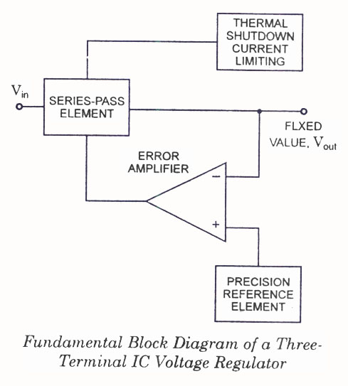
IC Voltage Regulators - Circuit diagram and block diagram of linear, fixed, adjustable (positive and negative), and switching voltage regulators. IC voltage regulators are essential components in electronic circuits, providing stable output voltages from a varying input voltage source. They...
The need for a device that can detect and extinguish a fire on its own is long past due. Many house fires originate when someone is either sleeping or not home. With the invention of such a device, people...
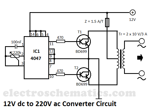
This DIY 12V to 220V voltage converter is built with the CMOS 4047, which serves as the main component of this compact voltage converter that transforms 12V DC into 220V AC. The 4047 is configured as an astable multivibrator,...