
time delay relay circuit
A proposed circuit design can be implemented using a NE555 timer configured in a monostable mode. The circuit will consist of the following components: a NE555 timer, a 12V relay, a magnetic reed switch, a capacitor, a resistor, and a transistor (2N3055 or a suitable alternative).
1. **NE555 Timer Configuration**: The NE555 timer will be set up in monostable mode. When the magnetic reed switch closes, it will trigger the NE555 timer. The timing duration can be set using a resistor (R) and a capacitor (C) connected to the timing pins of the NE555. The time delay can be adjusted to achieve a delay of 10-20 seconds based on the RC time constant.
2. **Transistor Driver**: A transistor, such as a 2N3055, will be used to drive the relay coil. The output of the NE555 timer will connect to the base of the transistor through a current-limiting resistor. This configuration allows the NE555 to control the higher current required to energize the relay coil, while also providing isolation between the timer and the relay.
3. **Relay and Load**: The relay will be connected in such a way that when it is energized, it interrupts the fuel control circuit, effectively shutting down the engine. The relay should be rated to handle the load current of 12V and 160mA.
4. **Reset Functionality**: The circuit will include a mechanism to reset the timer if the float switch opens during the delay period. This can be achieved by connecting the float switch to the reset pin of the NE555 timer, ensuring that any interruption in the switch state will reset the timer.
5. **Protection Circuitry**: To protect against voltage spikes and noise from the automotive environment, it is advisable to include a diode in parallel with the relay coil (flyback diode) to prevent back EMF from damaging the circuit. Additionally, capacitors may be placed across the power supply lines for filtering.
6. **Final Assembly**: The entire circuit can be assembled on a stripboard or PCB, ensuring that all connections are secure and that the components are rated for automotive use. Testing should be conducted to verify the functionality of the timer and relay operation under varying conditions.
This design addresses the requirements for a time-delay circuit to prevent unintended engine shutdowns due to fuel slosh while providing clear guidelines for assembly and operation.A diesel tractor that has a magnetic reed switch in the fuel tank to indicate low fuel. This switch is open when there is fuel in the tank, and closes when the level drops below it. When this switch closes a 12v relay is energized to disengage the fuel control and shuts off the engine. The problem is, sloshing fuel causes the float switch to intermittently open/close, which shuts off the engine!
What I am looking for is a time-delay circuit, so that when the float switch closes a delay of 10-20 seconds starts. If the switch STAYS closed longer than 20 seconds, the delay timer energizes the 12v relay and kills the engine. If the float switch OPENS during that 10-20 seconds, the timer needs to reset. My electronics experience is limited, and I have looked at perhaps a 555 chip to do this, but I cannot figure out the reset portion at all.
Could someone show me a circuit diagram to do what I need Any and all help is greatly appreciated! ! While I can understand a schematic and get something assembled, I really don`t know that much about individual transistors and their abilities/functions. and so will need a pretty complete schematic to pull this off. Guess I need some skoolin`! does this fit my criteria correctly At first glance it appears to. I added the transistor to carry the load of the relay, which I believe is. 16 amps. I THINK I understand this! One question I have is: does this keep the relay energized after the time delay, or is it just a pulse that will energize then de-energize I would prefer it to keep the relay energized if possible.
In this circuit, the input will normally be low, Q1 will be turned on and the capacitor will be charged. Th 555 output will be low and the 2N3055 will be off. If I am understanding you correctly, then this is just what I need. The input (float switch) bounces up and down as the tractor is moving, so the input will flip back and forth from low(open) to high (closed), and this needs to NOT set the output high unless the float STAYS high (closed, due to the fuel level being low enough).
When the input flips to low before the capacitor discharges, the output remains low and the capacitor will recharge, effectively resetting the time-delay correct Why is a 2N3055 being used to drive a relay coil What`s the resistance or current of the coil I think I read. 16A (160mA). Seems like a whole lot of over kill. For that matter, you don`t need a transistor to drive a 160mA relay coil. The NE555 will drive it directly. If you`re using it for the reason of low side switching I can appreciate that but not the 2N3055. You will need to give details of the input and the output load if a final design is to be suggested. A 2N3055 may need a heat sink (depending on the load) and a FET may be a better option. You can do what you want with duke37`s 4093-based design, or a design based on a 555 (not the one you`ve dug out - something much simpler will do), or a circuit using a couple of transistors.
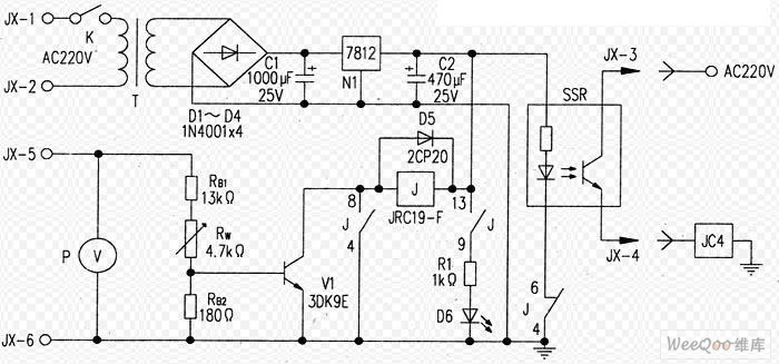
You would have to build it on a piece of stripboard. If you`re powering it from an automotive supply, the circuit will need protection against surges on the power supply and noise on the input. I THINK that the relay they call "H3Y" will do what you want. That number seems to be available from more than one source. I THINK the way it works is that when you apply power to it, it delays by an adjustable length of time (up to 30 seconds) before its contacts close, and if power is removed before the delay expires, the delay restarts from zero the next time power is applied.
IF that is how it works, you should be able to use it. Once the delay has expired and the contacts have closed, as long as the fuel tank microswitch stays closed, the relay contact should stay closed as well. I have not been able to find a description of how the relay works, apart from the fact that it`s an "adjustable time delay relay".
So I could be wrong. They`re only around USD 🔗 External reference
Related Circuits
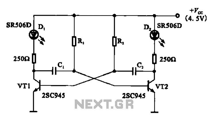
The multivibrator flashing light emitting diode (LED) display driver circuit can be utilized in toys, creating flashing effects in the eyes of animals or monsters. This circuit employs a multivibrator configuration, typically a 555 timer IC or a similar component,...
The FM302E-I-type FM transmitter exciter is manufactured by NEC Corporation, Japan, and features a 1210 motherboard. It utilizes direct frequency modulation of the carrier signal, employing phase-locked frequency stabilization and frequency synthesis techniques. The front power amplifier is based...
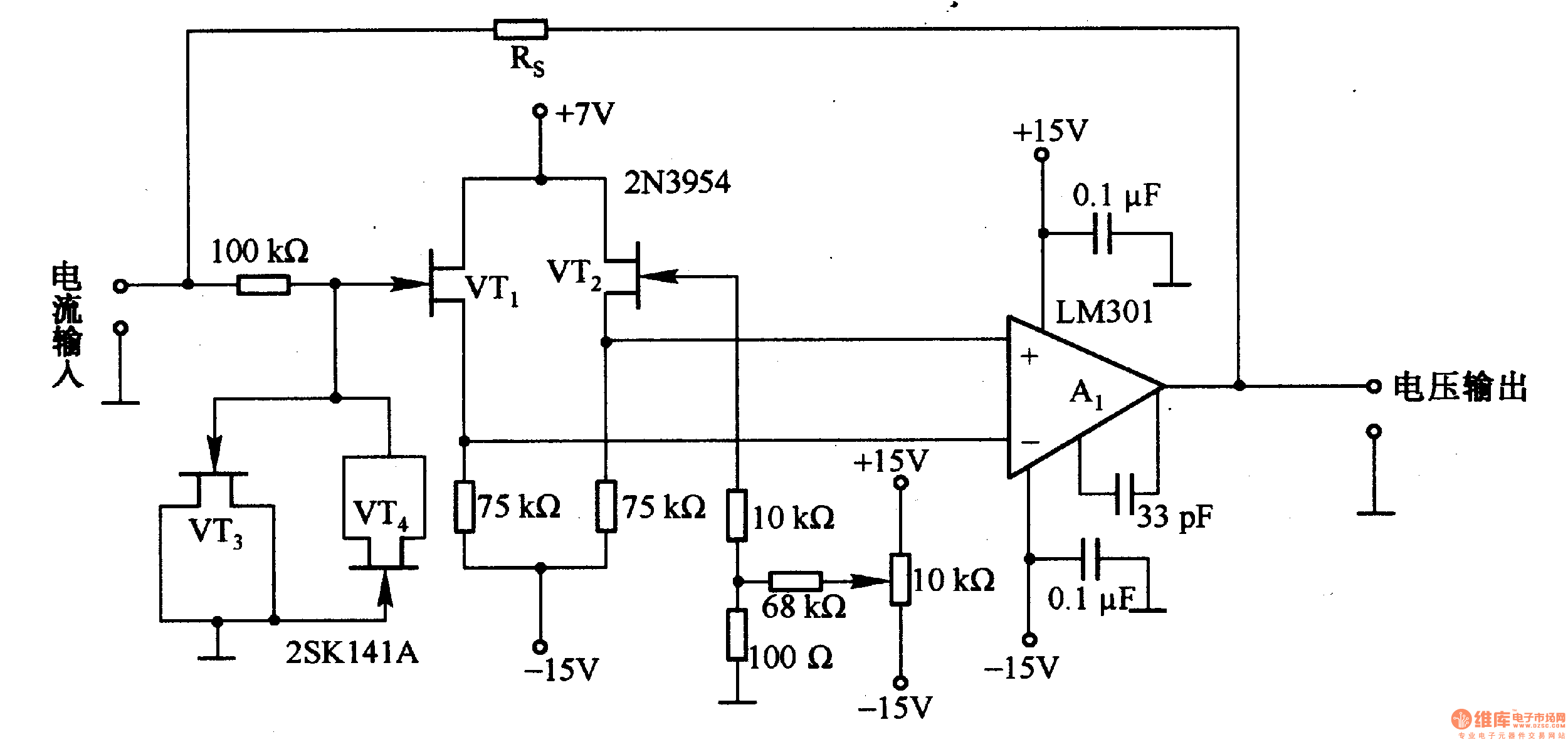
This is a low-input impedance conversion circuit with the reference resistor RS connected to the amplifier's feedback loop, resulting in an input impedance close to zero. The input current flows into the output end of the operational amplifier (Op-Amp)...
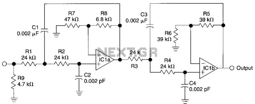
This circuit is a fourth-order low-pass filter designed for operation at kilohertz frequencies. The component values for resistors R1, R2, and capacitors C1, C2, as well as resistors R3, R4 and capacitors C3, C4 can be adjusted for functionality...
The circuit diagram represents a simple yet effective intercom system entirely based on transistors. It consists of three stages along with an RC amplifier. When the pushbutton S2 is pressed, the amplifier circuit around transistor T1 is activated. The intercom...
The RF oscillator using the inverter N2 and 10.7MHz ceramic filter is driving the parallel combination of N4 to N6 through N3. Since these inverters are in parallel, the output impedance will be low so that it can directly...